
Contact lens case

a contact lens and case technology, applied in the field of contact lens storage and care, can solve the problems of inconvenient care of contact lenses in this manner, difficulty in organizing and portability of contact lenses in-home and out-of-home, and one container can be quite easily misplaced or forgotten, so as to improve the functionality of handling and storage of contact lenses, convenience and aesthetic appeal to customers

Active Publication Date: 2005-04-28
ALCON INC
View PDF67 Cites 51 Cited by
  • Summary
  • Abstract
  • Description
  • Claims
  • Application Information

AI Technical Summary

Benefits of technology

The present invention is an improvement on lens cases used for storing and treating contact lenses. It has better functions like easy handling and storage of lenses, along with being more convenient and attractive than previous versions. Some versions can also be combined with a lens care solution container, making it easier for users to take care of their contacts while keeping track of one container instead of multiple ones.

Problems solved by technology

The technical problem addressed in this patent is the inconvenience and challenges in organizing and portability of contact lens care systems, which can include separate containers for the lens care solution and the lens case. Additionally, known lens cases have been found to be susceptible to leakage, inconvenient to open and close, and difficult to insert and remove contact lenses to and from their storage wells. The patent aims to provide an improved lens case for treatment, storage, and transport of contact lenses that meets these and other needs.

Method used


Image

  • Contact lens case
  • Contact lens case
  • Contact lens case

Examples


Embodiment Construction

[0026] The present invention may be understood more readily by reference to the following detailed description of the invention taken in connection with the accompanying drawing figures, which form a part of this disclosure. Unless defined otherwise, all technical and scientific terms used herein have the same meaning as commonly understood by one of ordinary skill in the art to which this invention belongs. Generally, the nomenclature used herein is well known and commonly employed in the art. Conventional methods are used for carrying out the disclosed procedures, such as those provided in the art and various general references. It is to be understood that this invention is not limited to the specific devices, methods, conditions or parameters described and / or shown herein, and that the terminology used herein is for the purpose of describing particular embodiments by way of example only and is not intended to be limiting of the claimed invention. Also, as used in the specificatio...


PUM


Abstract

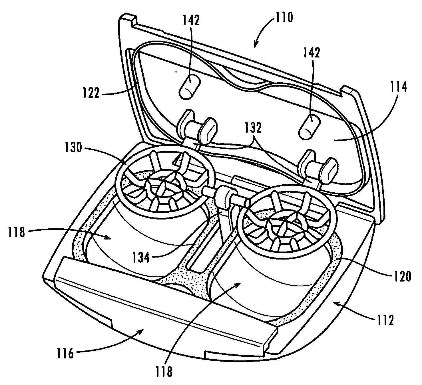
A contact lens case including a body or base portion with a pair of lens-receiving wells recessed therein, a cap or cover closable to form a substantially liquid-impermeable seal around the wells, and a latch or closure assembly engageable to secure the cover in its closed position. A compressible gasket around the wells assists in forming the seal with the cover. The wells include a primary bowl portion with a tapered secondary portion extending therefrom to assist in lens removal.

Description


Claims


Application Information

Patent Timeline
Owner ALCON INC
Learn More