Optical disc drive using noise reducing unit

a technology of optical disc drive and noise reduction unit, which is applied in the direction of record information storage, record carrier contruction details, instruments, etc., can solve the problems of increasing the noise of the optical disc, generating noise, and reducing the flow speed of air, so as to improve the structure and reduce the pressure difference between the inner and outer circumferences of the optical disc. , the effect of improving the structur

Inactive Publication Date: 2005-04-21
TS OPTICS CORP
View PDF15 Cites 9 Cited by
  • Summary
  • Abstract
  • Description
  • Claims
  • Application Information

AI Technical Summary

Benefits of technology

[0012] The present invention provides an optical disc drive having an improved structure in which a pressure difference between inner and outer circumferences of an optical disc is reduced, the flow speed of air is lowered, and noise caused by air turbulence in the optical disc drive and flow noise in the optical disc are reduced.
[0013] According to an aspect of the present invention, an optical disc drive comprises a main frame in which a turntable is provided; a tray on which the optical disc is mounted and which is slidable in the main frame; a cover, which covers a top surface of the main frame and includes a clamper to fix the optical disc in the turntable; and a noise reducer, which is disposed in the cover and causes air, generated by rotation of the optical disc, to circulate from an inner circumference to an outer circumference of the optical disc and from the outer circumference to the inner circumference thereof. According to this arrangement, this air flow reduces noise.

Problems solved by technology

Noise generated by the high-speed rotation of an optical disc in a high-speed and high-density optical disc drive has been a serious problem in the development of high performance optical disc drives.
The noise is generated as a result of various noise generating causes.
The noise escapes through a gap between a door and a main body case, increasing the whole noise of the optical disc.

Method used


Image

  • Optical disc drive using noise reducing unit
  • Optical disc drive using noise reducing unit
  • Optical disc drive using noise reducing unit

Examples


Embodiment Construction

[0021] Reference will now be made in detail to the embodiments of the present invention, examples of which are illustrated in the accompanying drawings, wherein like reference numerals refer to the like elements throughout. The embodiments are described below to explain the present invention by referring to the figures.

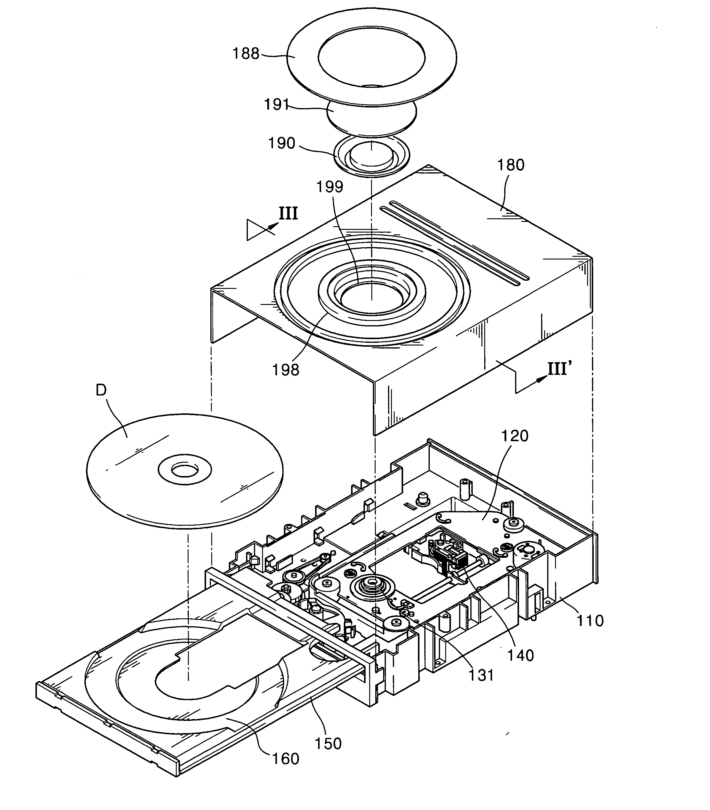
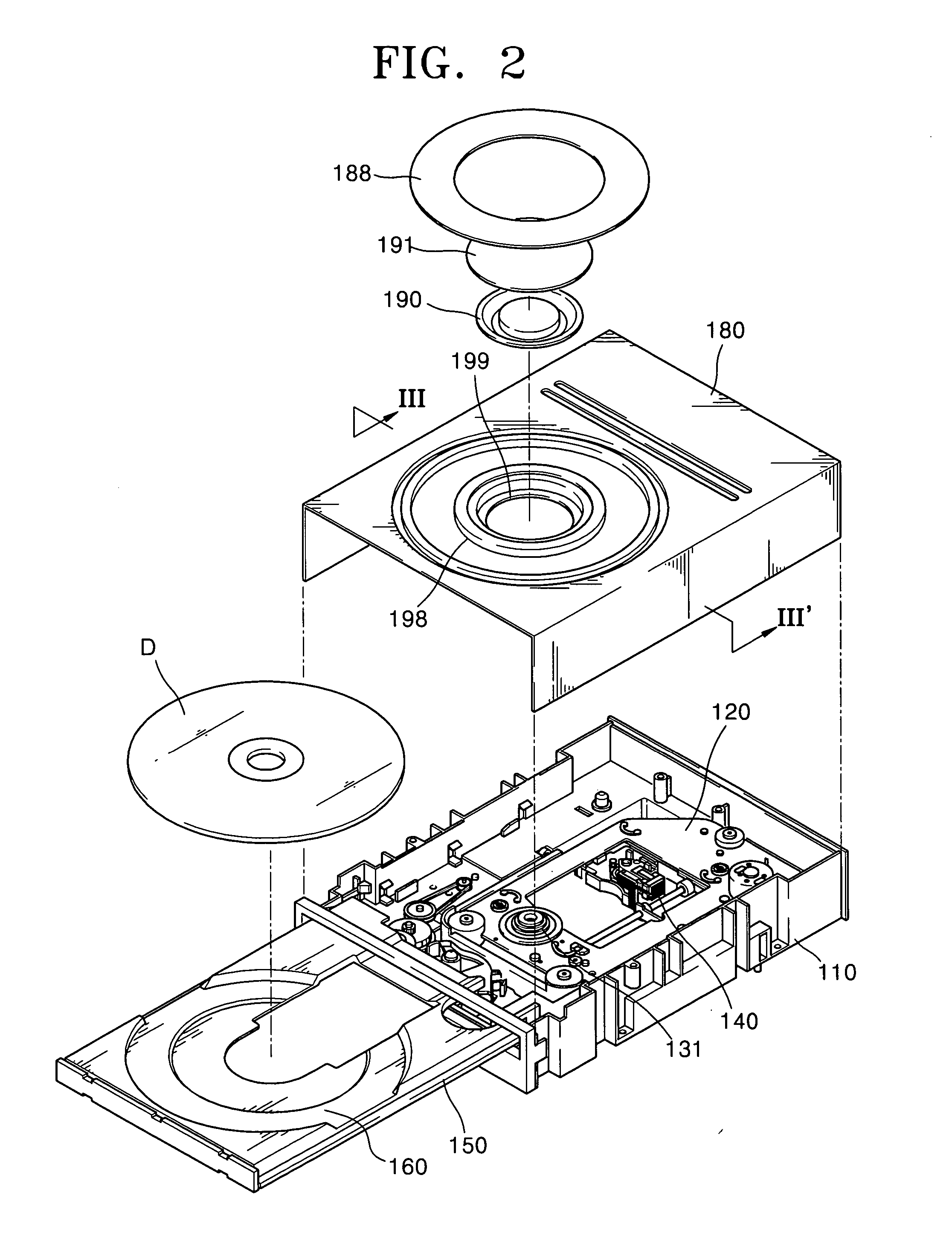
[0022] Referring to FIG. 2, an optical disc drive using a noise reducer according to an embodiment of the present invention includes a main frame 110, a tray 150, and a cover 180.

[0023] The main frame 110 includes a sub-chassis 120 which moves upwards and downwards with respect to the main frame 11. A turntable 131, on which an optical disc D is mounted, is disposed in the sub-chassis 120. A spindle motor (130 of FIG. 5), which rotates the turntable 131, and an optical pickup 140, which makes a reciprocating motion in a radial direction of the optical disc D and records information on the optical disc D or reproduces the information recorded on the optical disc D, a...


PUM

PropertyMeasurementUnit
circumferenceaaaaaaaaaa
air densityaaaaaaaaaa
heightaaaaaaaaaa

Abstract

An optical disc drive including a main frame in which a turntable is provided; a tray on which the optical disc is mounted and which is slidable in the main frame; a cover, which covers a top surface of the main frame and includes a clamper to fix the optical disc in the turntable; and a noise reducer, which is disposed in the cover and causes air generated by rotation of the optical disc circulate from an inner circumference to an outer circumference of the optical disc and from the outer circumference to the inner circumference thereof, thereby reducing noise.

Description

CROSS-REFERENCE TO RELATED APPLICATIONS [0001] This application claims the priority of Korean Patent Application No. 2003-50507, filed on Jul. 23, 2003, in the Korean Intellectual Property Office, the disclosure of which is incorporated herein in its entirety by reference. BACKGROUND OF THE INVENTION [0002] 1. Field of the Invention [0003] The present invention relates to an optical disc drive, and more particularly, to an optical disc drive using a noise reducing unit for reducing noise generated by air flow due to the rotation of a disc. [0004] 2. Description of the Related Art [0005] Typically, optical disc drives are devices which write or read information by radiating light on an optical medium (hereinafter, referred to as an optical disc) having a disc shape, such as a compact disc (CD) or a digital versatile disc (DVD). [0006]FIG. 1 shows a structure of a conventional optical disc drive. Referring to FIG. 1, the conventional optical disc drive includes a main frame 11, a tray...

Claims


Application Information

Patent Timeline
Patent Type & Authority Applications(United States)
IPC IPC(8): G11B17/04G11B33/08G11B33/14
CPCG11B17/056G11B33/1486G11B33/08
Inventor LEE, SANG-YUNCHOI, MYUNG-RYULCHO, EUN-HYOUNGOH, SUK-IL
Owner TS OPTICS CORP
Why Eureka
Try Eureka