
Transfer unit used with image forming apparatus

Inactive Publication Date: 2005-04-21
S PRINTING SOLUTION CO LTD
View PDF21 Cites 6 Cited by
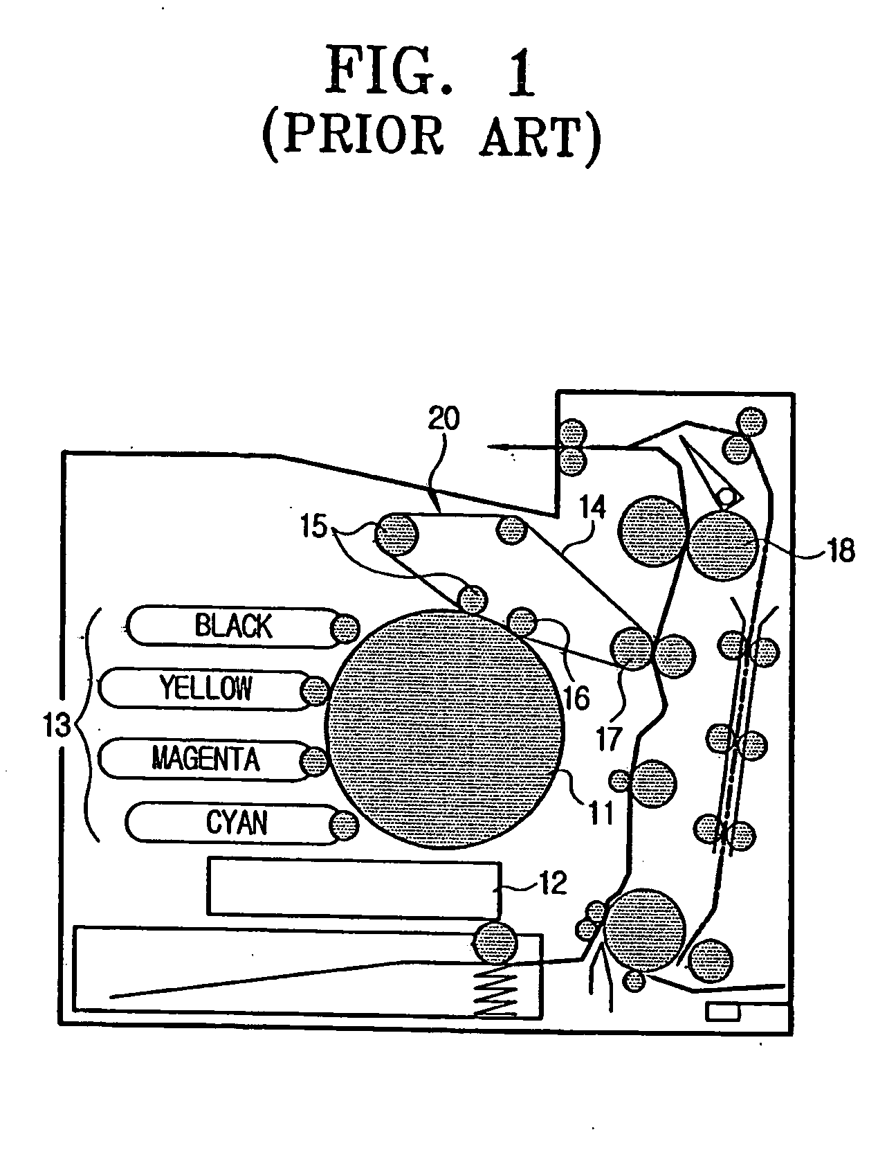
  • Summary
  • Abstract
  • Description
  • Claims
  • Application Information

AI Technical Summary

Benefits of technology

[0016] In order to overcome the above-mentioned and / or other problems, it is an aspect of the present general inventive concept to provide a transfer unit used with an image forming apparatus having an improved structure to provide a more secure and facile operation in replacing and mounting the transfer unit, and capable of controlling a position thereof with respect to a contacting object, such as a photoconductive unit.
[0022] In an aspect of the present general inventive concept, tension of the transfer belt can be smaller when the piece is mounted in the transfer unit, than when the piece is removed from the transfer unit. The upper housing may further include a guide member which guides a mounting position of the transfer unit when being mounted in the main body of the image forming apparatus.

Problems solved by technology

As the transfer unit is used a long period of time, accuracy thereof gradually deteriorate.
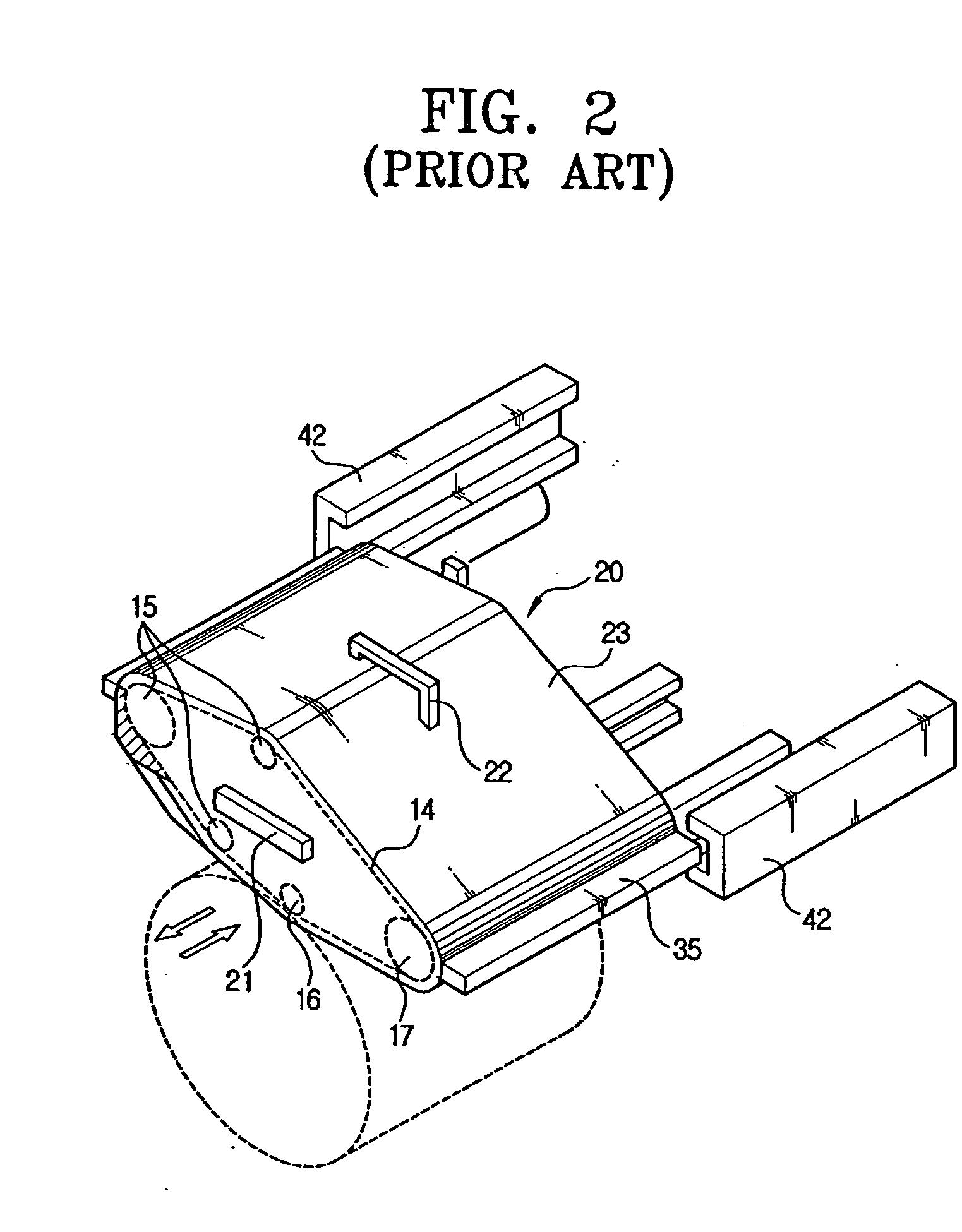
Therefore, if the user handles the transfer housing 23 carelessly, i.e., pulling the transfer housing 23 too roughly, there is a risk of damaging the transfer housing 23 by dropping it when the guide member 35 is separated from the guide rail 42.
Thus, the replacing process of the transfer housing 23 becomes troublesome.

Method used


Image

  • Transfer unit used with image forming apparatus
  • Transfer unit used with image forming apparatus
  • Transfer unit used with image forming apparatus

Examples


Embodiment Construction

[0037] Reference will now be made in detail to the embodiments of the present general inventive concept, examples of which are illustrated in the accompanying drawings, wherein like reference numerals refer to the like elements throughout. The embodiments are described below in order to explain the present invention by referring to the figures.

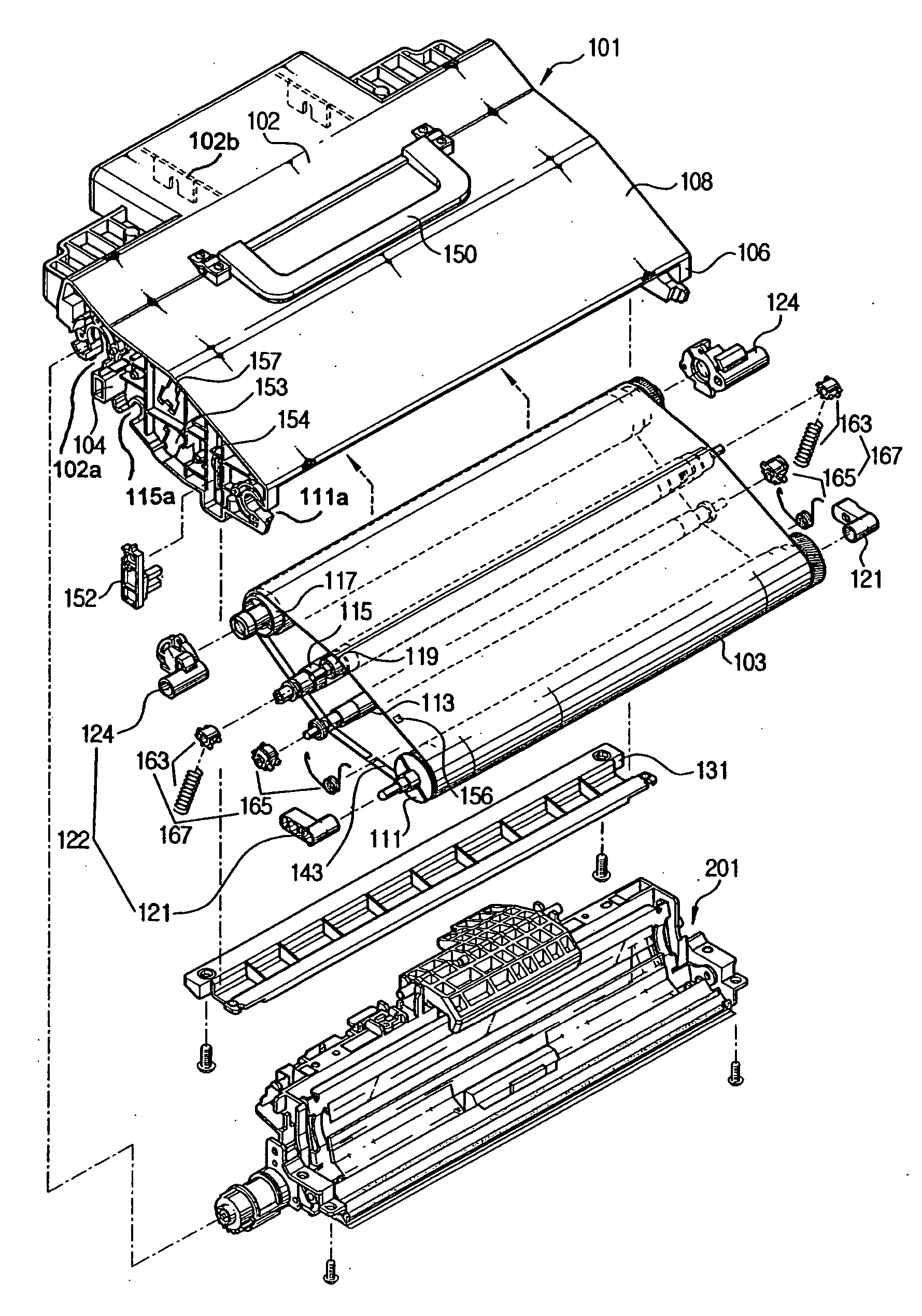
[0038] Referring to FIGS. 3 to 5, a transfer unit 100 according to an embodiment of the present general inventive concept may include an upper housing 101 and a lower housing and can be detachably connected to an image forming apparatus in a vertical direction.

[0039] The upper housing 101 may include a transfer belt 103 having an image forming surface of an endless track type. An upper surface of the upper housing 101 can be provided with a rotatable handle 150.

[0040] An upper side of the upper housing 101 can be closed tightly, and a lower side of the upper housing 101 can be open. Therefore, as shown in FIG. 6, the upper housing 101 can b...


PUM


Abstract

A transfer unit used with an image forming apparatus includes an upper housing having a transfer belt of an endless track structure to transfer an image from a photoconductive unit of a main body of the image forming apparatus, and a plurality of rollers to support the transfer belt to rotate therein, and a lower housing removably connected to the upper housing, and having a cleaning unit to clean the transfer belt. The transfer unit is removably mounted to the main body of the image forming apparatus. Accordingly, the transfer unit is facile to be connected to and separated in a vertical direction from the main body of the image forming apparatus. Further, it is convenient to replace the transfer unit since the relative position thereof can be controlled with respect to a contacting object, such as the photoconductive unit.

Description

CROSS-REFERENCE TO RELATED APPLICATIONS [0001] This application claims the benefit of Korean Application No. 2003-73276, filed Oct. 21, 2003, in the Korean Intellectual Property Office, the disclosure of which is incorporated herein by reference. BACKGROUND OF THE INVENTION [0002] 1. Field of the Invention [0003] The present general inventive concept relates to a transfer unit used with an image forming apparatus, and more particularly, a transfer unit detachably mounted in a vertical direction in an image forming apparatus and having a transfer belt of an endless track structure to transfer an image from a photoconductive unit of a main body of the image forming apparatus, an upper housing having a plurality of rollers to support the transfer belt and move therein, and a lower housing having a cleaning unit of the transfer belt. [0004] 2. Description of the Related Art [0005] Generally, an image forming apparatus, i.e., a printer or a photocopier, includes a transfer unit to receiv...

Claims


Application Information

Patent Timeline
IPC IPC(8): G03G15/14G03G15/16G03G21/16
CPCG03G2221/1642G03G2221/1684G03G21/168G03G21/1647G03G15/1605G03G15/14
Inventor KYUNG, MYUNG-HOPARK, MUN-BAE
Owner S PRINTING SOLUTION CO LTD
Learn More