
Video encoding method and video encoding apparatus

a video encoding and video encoding technology, applied in the field of video compression and encoding technology, can solve the problems of low frame rate, disadvantageous video becoming unnatural, and affecting the so as to prevent the deterioration of visual quality of decoded video, the effect of unified decoded video and preventing the decrease of frame ra

Inactive Publication Date: 2005-04-21
FURUKAWA RIEKO +2
View PDF15 Cites 43 Cited by
  • Summary
  • Abstract
  • Description
  • Claims
  • Application Information

AI Technical Summary

Benefits of technology

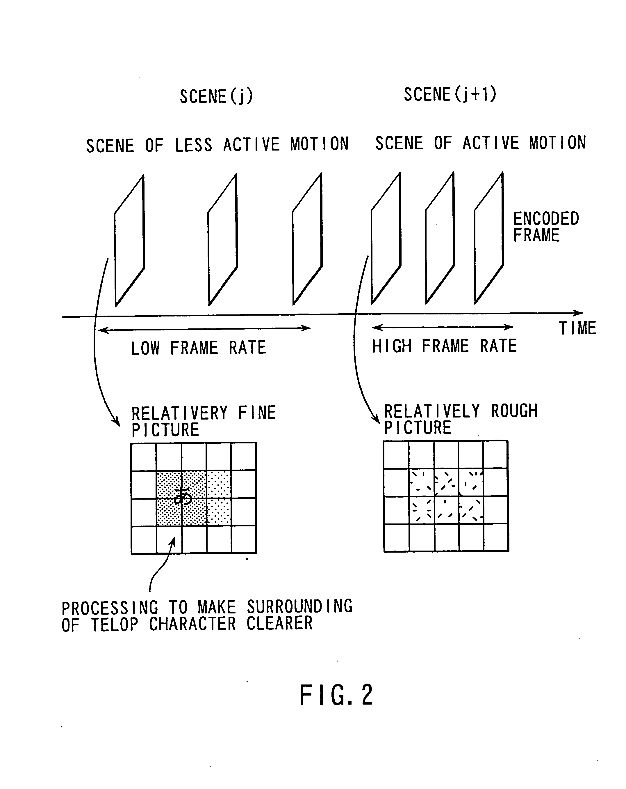
"The present invention provides a video encoding method and apparatus that can efficiently encode video with good picture quality while maintaining a target data size. The encoded parameters are determined based on the motion of objects and the content of the video scene. The video feature amounts based on the motion of objects and camera motion are reflected on the encoded parameters, resulting in a good decoded video unified for each scene. The invention is also applicable to video encoding of the same video file twice or more, where the encoded parameters are corrected to achieve the target data size. The technical effects of the invention are improved video quality and efficient data size control."

Problems solved by technology

With this method, however, if the number of coded bits generated in a previous frame is large, frame skipping is conducted until the buffer capacity becomes not more than the frame skip threshold.
Due to this, the distance between the frame and the next frame becomes too wide, with the result that video disadvantageously becomes unnatural.
For that reason, frame rate become too low on a scene in the video on which an object moves actively and the motion of the object becomes unnatural.
Besides, due to the inappropriate quantization width, the picture may be distorted to thereby disadvantageously find it difficult to visually recognize the picture.
The two-pass encoding, however, has the same problems as those described above since encoding parameters are conventionally, basically set irrespectively of the contents of a video.
Due to this, the frame rate suddenly decreases on a scene in the video on which an object moves actively and the motion of the object becomes unnatural.
Also, due to the inappropriate quantization width, the video may be distorted.
Thus, the conventional video encoding apparatus has a disadvantage in that the deterioration of picture quality tends to be conspicuous.

Method used


Image

  • Video encoding method and video encoding apparatus
  • Video encoding method and video encoding apparatus
  • Video encoding method and video encoding apparatus

Examples


Embodiment Construction

[0031] The embodiment of the present invention will be described hereinafter with reference to the accompanying drawings.

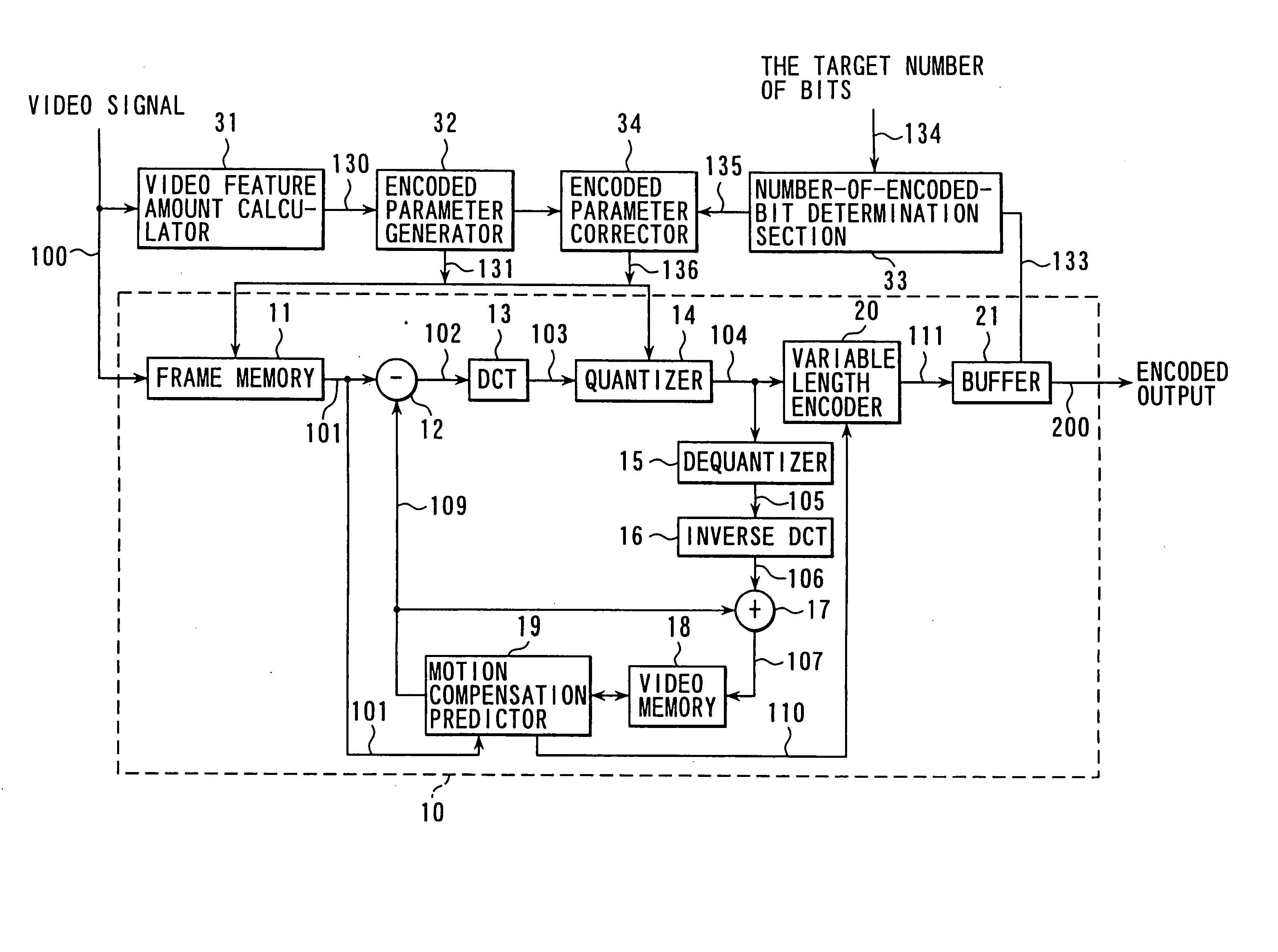
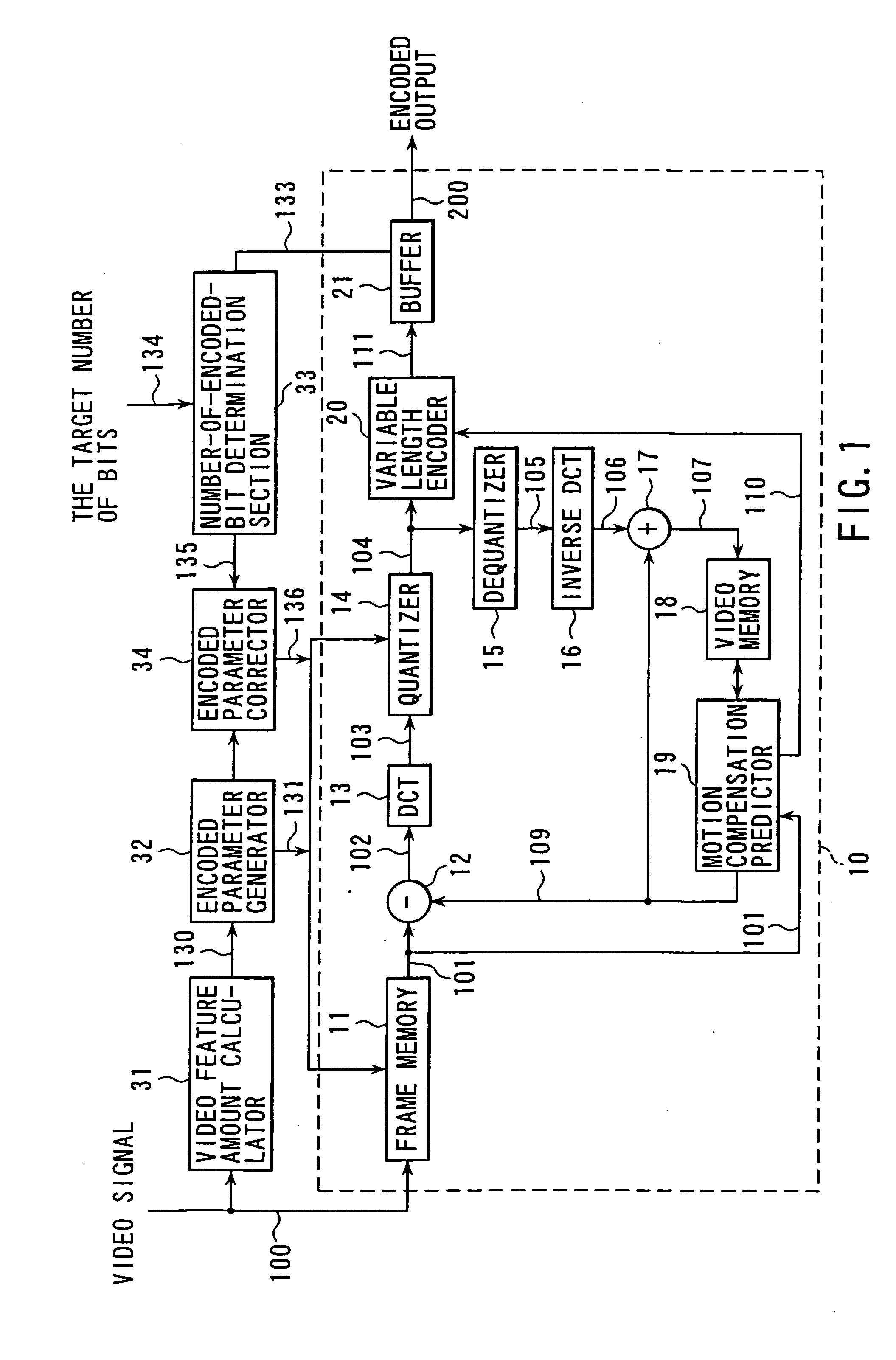
[0032]FIG. 1 is a block diagram showing the construction of a video encoding apparatus in one embodiment according to the present invention. As shown therein, an input video signal 100 is a video signal reproduced by a video recording / reproducing apparatus such as a digital VTR or a DVD system capable of repeatedly reproducing the same signal. The signal 100 is inputted into an encoder section 10. In this embodiment, the encoder section 10 is the same in construction as a video encoding apparatus based on the MPEG scheme.

[0033] In the encoder section 10, a video signal of a to-be-encoded frame selected from the input video signal 100 is first stored in a frame memory 11. The video signal 101 of the to-be-encoded frame read from the frame memory 11 is inputted into a subtracter 12 and a motion compensation predictor 19. The motion compensation predictor 19 includ...


PUM


Abstract

An video encoding method and a video encoding apparatus wherein an input video signal is divided into a plurality of temporally continuous scenes each including at least one frame, statistical feature amounts are calculated for each of the scenes, encoded parameters are generated for each of the scenes based on said statistical feature amounts, and the input image signal is encoded using the encoded parameters.

Description

BACKGROUND OF THE INVENTION [0001] The present invention relates to a video compression and encoding technology such as an MPEG scheme utilized in a video transmission system and a video database system through the Internet or the like. The present invention particularly relates to a video encoding method and a video encoding apparatus capable of providing a unified decoded video for each scene, which is easy to see without increasing data size, by encoding data in accordance with encoded parameters based on the content of scenes. [0002] The MPEG scheme, which is an international standard for video encoding, is a technique for compressing a video by a combination of motion compensation prediction, discrete cosine transformation and variable length coding, as is well known. The MPEG scheme is described in detail in, for example, Reference 1: “MPEG”, The Institute of Television Engineers edition, Ohmsha, Ltd.). [0003] In a conventional video encoding apparatus based on the MPEG scheme...

Claims


Application Information

Patent Timeline
Patent Type & Authority Applications(United States)
IPC IPC(8): H04N7/26H04N7/46H04N7/50
CPCH04N19/139H04N19/198H04N19/172H04N19/196H04N19/15H04N19/102H04N19/61H04N19/124H04N19/132H04N19/14H04N19/17H04N19/179H04N19/192H04N19/527H04N19/587H04N19/87H04N19/176
Inventor FURUKAWA, RIEKONAGAI, TAKESHIKIKUCHI, YOSHIHIRO
Owner FURUKAWA RIEKO
Learn More