
Energy storage device

a technology of energy storage and energy storage, which is applied in the direction of electrochemical generators, secondary cells servicing/maintenance, cell components, etc., can solve the problems of low efficiency at high load currents, poor accommodation of wide variations in load currents, and battery life becoming compromised

Inactive Publication Date: 2005-04-21
CAP XX LTD
View PDF19 Cites 28 Cited by
  • Summary
  • Abstract
  • Description
  • Claims
  • Application Information

AI Technical Summary

Benefits of technology

"The present invention provides an energy storage device that includes a housing with two terminals, an electrochemical device, and a capacitor. The electrochemical device provides a first current to the load, while the capacitor provides a second current to the load in parallel with the electrochemical device. This design allows for a faster current and a higher energy density, and can be used in various battery designs. The capacitor can be wrapped around the electrochemical device or disposed within the housing. The energy storage device can be used in various applications such as batteries and electric double layer supercapacitors."

Problems solved by technology

These batteries suffer firm several limitations including poor accommodation of wide variations in load currents and a low efficiency at high load currents.
However, where varying load cod and particularly high load currents for high power applications are encountered, the battery life becomes compromised.
However, should the operator require a higher torque for a short period, a pulse or surge of power will be required.
Although this demand for transitory power is common in many electrical appliances and devices, it is not efficiently provided by a battery.
Similar problems to that foreshadowed above for the drill arise for other devices whether they are toys, electronic games, mobile or cellular phones, portable or laptop computers or the like.

Method used


Image

  • Energy storage device
  • Energy storage device
  • Energy storage device

Examples


Embodiment Construction

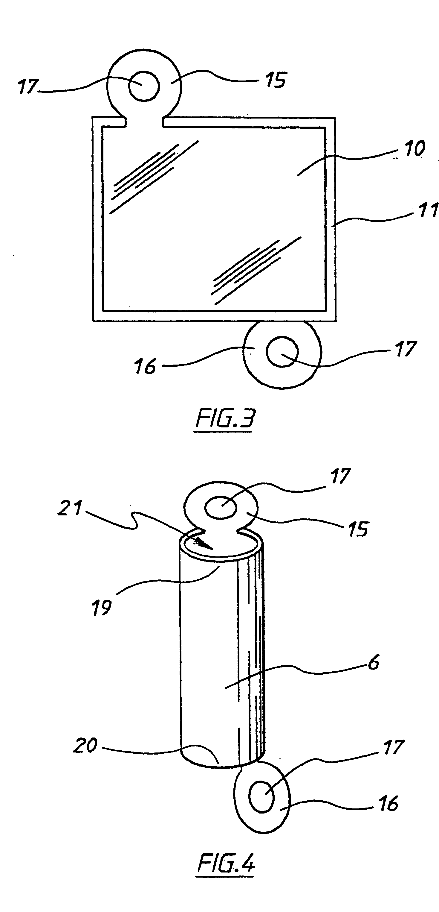
[0059] As shown in FIG. 3, supercapacitor 6 is formed from two like opposed rectangular aluminium sheet electrodes 10 which are maintained in a spaced apart overlying configuration by an intermediate separator 11. Each electrode includes a coating of activated carbon for providing a high surface area. Moreover, each electrode includes a protruding tab, which are separately numbered 15 and 16. The tabs includes respective central apertures 17 and are configured such that they protrude from opposite edges of the respective sheets.

[0060] The elements shown in FIG. 3 are placed in a package with only tabs 15 and 16 protruding. An electrolyte is placed in the package before it is sealed. This arrangement is then wound to provide the tubular supercapacitor 6, as best shown in FIG. 4. The supercapacitor is hollow and extends axially between a first end 19 and a second opposed end 20. Each of the ends includes an apt 21.

[0061] The internal diameter of the supercapacitor is such as to comp...


PUM

PropertyMeasurementUnit
thicknessaaaaaaaaaa
diameteraaaaaaaaaa
capacitanceaaaaaaaaaa

Abstract

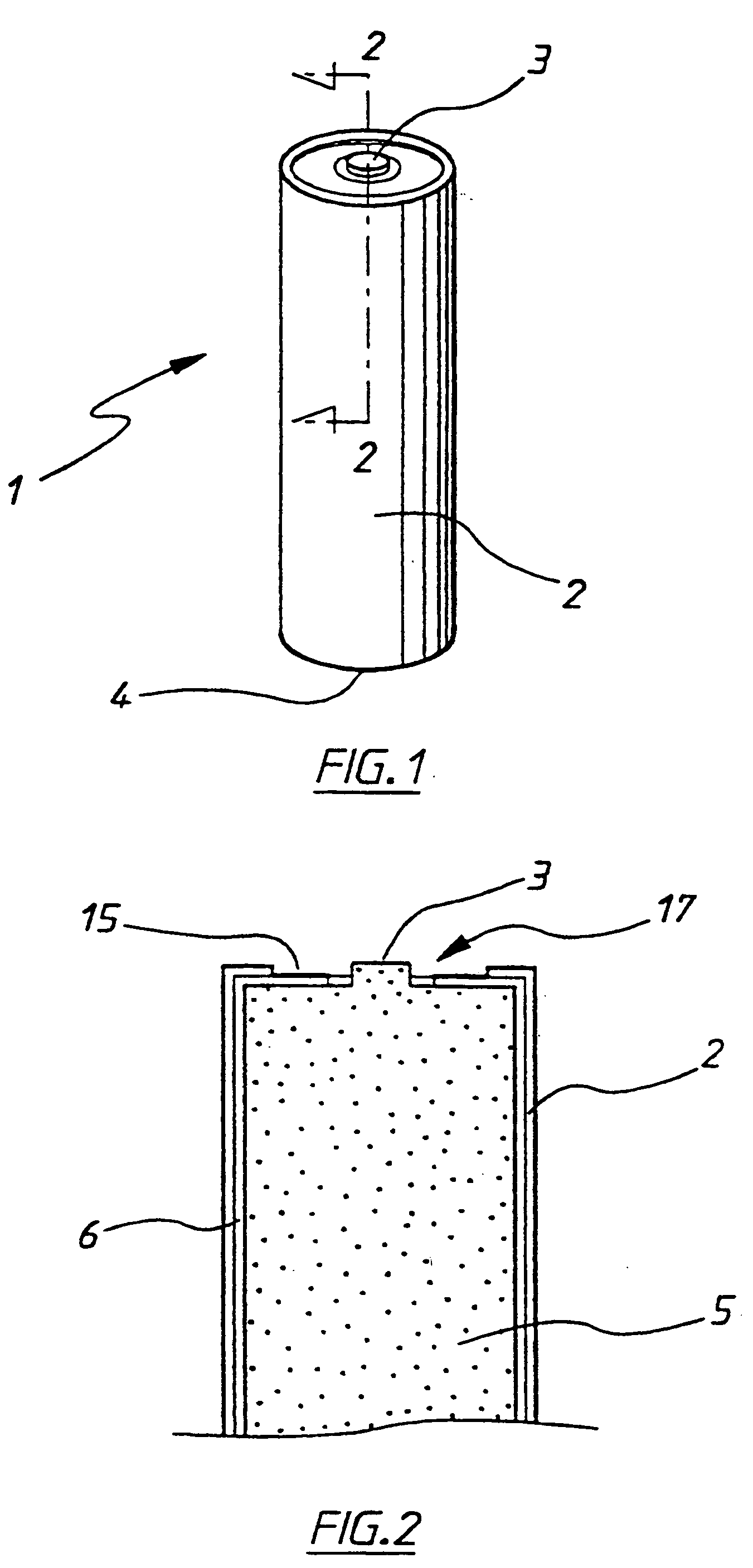
An energy storage device includes a cylindrical shrink wrap housing having two opposed metal terminals. An electrochemical device in the form of a dry cell alkaline battery is disposed within the housing for providing an electrical potential between the terminals. An electric double layer supercapacitor is wrapped around and mounted to the housing and connected to the terminals in parallel with the battery.

Description

[0001] The present invention relates to an energy storage device. [0002] The invention has been developed primarily for providing an energy store for portable electrical devices such as mobile telephones and laptop computers and will be described hereinafter with reference to that application. However, the invention is not limited to that particular field of use and is also applicable to other electrical loads including those that are remote from mains supplies or those that have high peak currents and low average currents. BACKGROUND OF THE INVENTION [0003] Dry cell and alkaline batteries, both in primary and sec ry form, are used in a wide variety of applications. Primary batteries are once only or disposable batteries, while secondary batteries are rechargeable. Batteries of these kinds are used in mobile and cellular telephones, portable computers, cordless electric power tools, household appliances, cameras, and other mobile devices to name but a few. These form of batteries ar...

Claims


Application Information

Patent Timeline
Patent Type & Authority Applications(United States)
IPC IPC(8): H01G9/28H01G15/00H01M10/052H01M10/42H01M16/00H01M50/107
CPCH01G9/155H01G11/08H01G11/82H01M2/0207Y02E60/13H01M10/052H01M10/42H01M10/4264Y02E60/122H01M2/022H01M50/107
Inventor MAHON, PETER JOHN
Owner CAP XX LTD
Learn More