Light control device and imaging device

a technology of light control device and imaging device, which is applied in the direction of static indicating device, television system, instruments, etc., can solve the problems of deteriorating the light absorption effect, deteriorating the driving efficiency of the guest-host liquid crystal element, and reducing the quantity of at least ultraviolet rays applied to the guest-host liquid crystal element, and achieving stable high-efficiency drive of the liquid crystal element. , the effect of significant reduction of the quantity of at least ultraviolet rays

Inactive Publication Date: 2005-04-14
SONY CORP
View PDF9 Cites 6 Cited by
  • Summary
  • Abstract
  • Description
  • Claims
  • Application Information

AI Technical Summary

Benefits of technology

[0017] In the present invention, at least one of the filter material absorbing at least ultraviolet rays and the reflecting material reflecting at least ultraviolet rays is disposed on the light incident side of the guest-host liquid crystal element, and thus the quantity of at least ultraviolet rays applied to the guest-host liquid crystal element is significantly decreased. Therefore, the component material such as the dichroic dye molecule in the guest-host liquid crystal element is neither optically decomposed nor optically deteriorated by ultraviolet rays, thereby permitting stable high-efficiency drive of the liquid crystal element.

Problems solved by technology

In the use of a conventional guest-host liquid crystal cell, a dichroic dye molecule is used in a liquid crystal element, and there is thus the problem of deteriorating the dye molecule by excessive ultraviolet irradiation.
Therefore, the color of the molecule is changed or faded to deteriorate the light absorption function basically possessed by the molecule, thereby deteriorating the light absorption effect and the driving efficiency of the guest-host liquid crystal element.

Method used


Image

  • Light control device and imaging device
  • Light control device and imaging device
  • Light control device and imaging device

Examples


Embodiment Construction

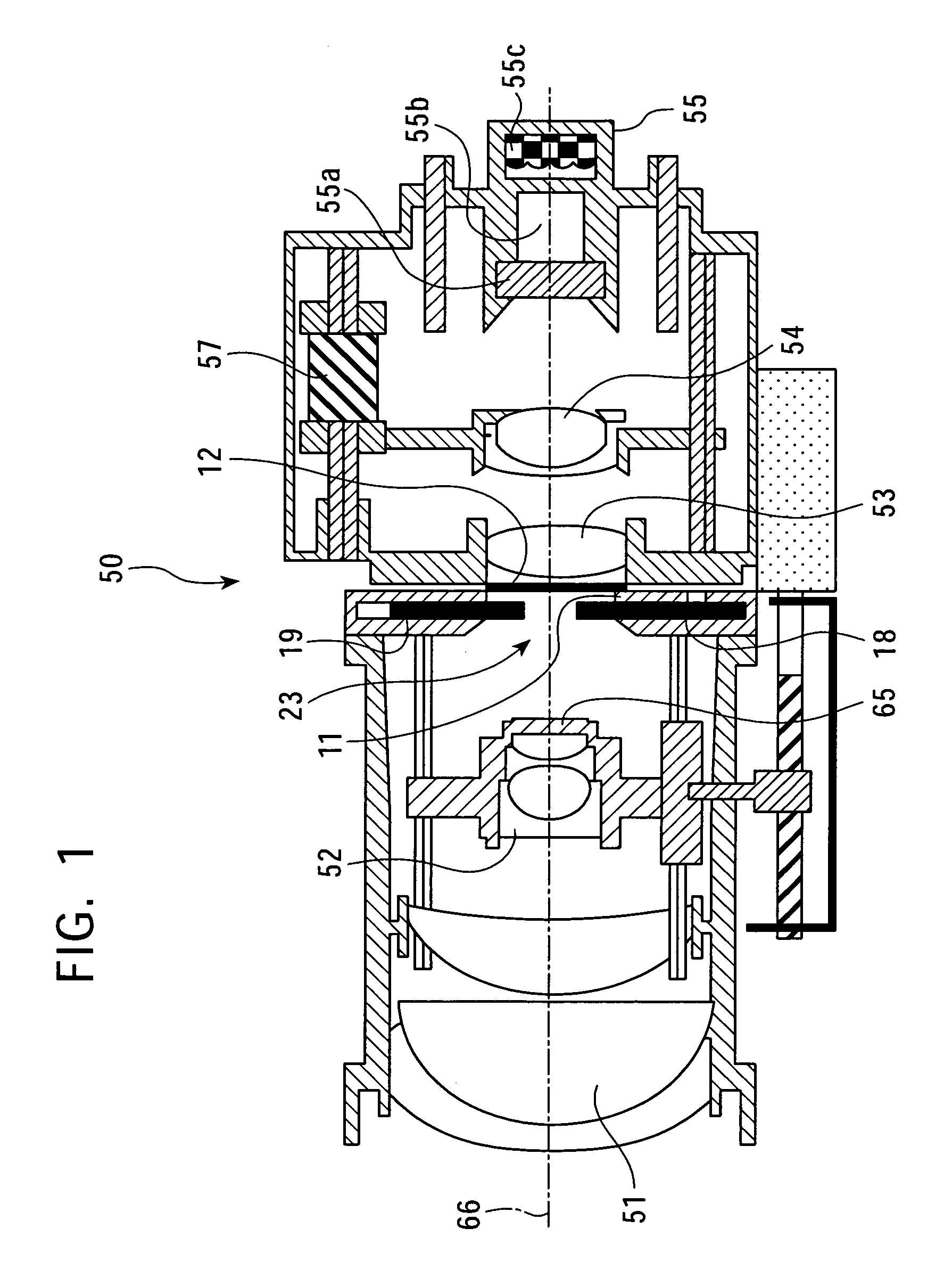
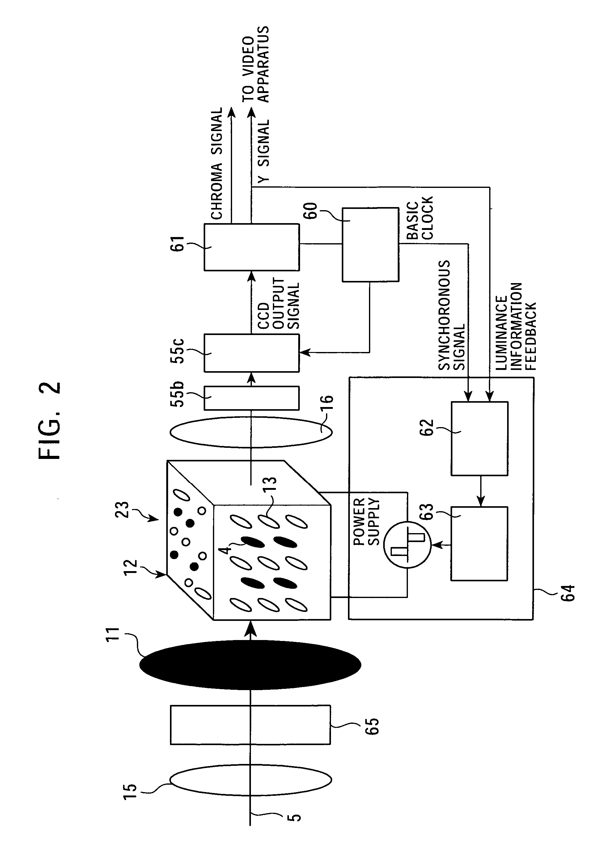
[0034] In the present invention, a filter material or a reflecting material comprises at least one selected from an ultraviolet cut-off or reflecting film, ultraviolet cut-off or reflecting coated glass, and ultraviolet absorbing or reflecting glass, and the filter material or the reflecting material is preferably provided at least in the same area as the section of an effective optical path of incident light, for sufficiently cutting off or reflecting ultraviolet rays.

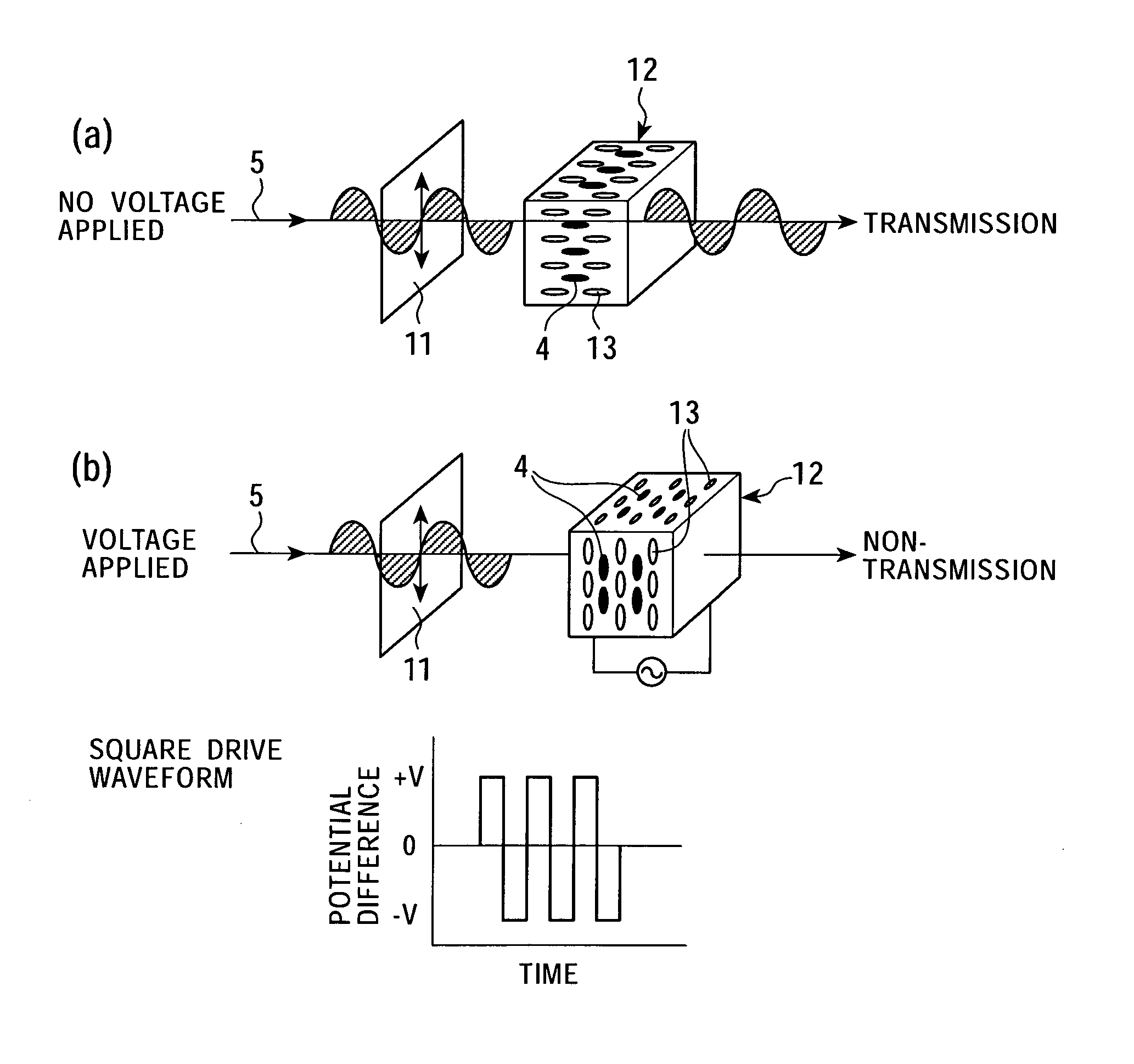
[0035] Also, a polarizer is disposed in the effective optical path of light incident on a liquid crystal element so that the polarizer can be taken in and out of the effective optical path, for making a quantity of light uniform, as described below.

[0036] When the liquid crystal element is disposed to be exposed from the outer surface of a device, preferably, the filter material or the reflecting material is provided on the light incidence side of the liquid crystal element, and the filter material or the reflecting...


PUM

PropertyMeasurementUnit
light transmittanceaaaaaaaaaa
optical densityaaaaaaaaaa

Abstract

A light control device and an imaging device suitable for the effective and stabilized driving of a Guest-Host type liquid crystal element. A light control device which is provided with a light controlling GH cell and a UV cut filter provided on the light incident side of the GH cell and which is therefore reduced significantly in the quantity of ultraviolet ray applied to the GH cell, thereby preventing the photodecomposition or photodegradation of materials constituting a liquid crystal layer in the GH cell; and an imaging device such as a CCD camera having this light control device disposed on the optical path thereof.

Description

TECHNICAL FIELD [0001] The present invention relates to a light control device, for example, for controlling the quantity of incident light and emitting the light, and an imaging device using the light control device. BACKGROUND ART [0002] In general, a polarizer plate is used for a light control device using a liquid crystal cell. As the liquid crystal cell, for example, a TN (Twisted Nematic) liquid crystal cell or a guest-host (GH) liquid crystal cell is used. [0003]FIGS. 15A and 15B are schematic drawings each showing the principle of operation of a conventional light control device. The light control device mainly comprises a polarizer 1 and a GH cell 2. Although not shown in the drawings, the GH cell 2 is sealed between two glass substrates, and comprises an operating electrode made of ITO (Indium tin oxide) or the like, and a liquid crystal orientation film such as a polyimide film or the like (this applies to the description below). Also, a positive liquid crystal molecule 3...

Claims


Application Information

Patent Timeline
Patent Type & Authority Applications(United States)
IPC IPC(8): G02B5/00G02B27/28G02F1/133G02F1/1335G02F1/139H04N5/225H04N5/238
CPCG02B5/005G02B27/281G02F1/13306H04N5/238G02F1/13725H04N5/2254G02F1/133509H04N23/55H04N23/75G02F1/1335
Inventor UDAKA, TORUNITO, KEIICHIYANAGIDA, TOSHIHARUKAWABATA, MASARU
Owner SONY CORP
Why Eureka
Try Eureka