
Integrated three phase separator

a three-phase separator and integrated technology, applied in the direction of separation process, liquid displacement, borehole/well accessories, etc., can solve the problems of liquid surges, liquid slugs entering the separator, periodic slugs or surges of liquid into the separator vessel, etc., to achieve the effect of preventing liquid surges and preventing liquid surges

Active Publication Date: 2005-04-14
PROCESS EQUIP & SERVICE
View PDF20 Cites 12 Cited by
  • Summary
  • Abstract
  • Description
  • Claims
  • Application Information

AI Technical Summary

Problems solved by technology

This can result in periodic slugs of liquid entering the separator.
Since the separator operates by gravity, periodic slugs or surges of liquid into the separator vessel are counterproductive to the separation process.

Method used


Image

  • Integrated three phase separator
  • Integrated three phase separator
  • Integrated three phase separator

Examples


Embodiment Construction

[0026] The embodiments discussed herein are merely illustrative of specific manners in which to make and use the invention and are not to be interpreted as limiting the scope of the instant invention.

[0027] While the invention has been described with a certain degree of particularity, it is to be noted that many modifications may be made in the details of the invention's construction and the arrangement of its components without departing from the spirit and scope of this disclosure. It is understood that the invention is not limited to the embodiments set forth herein for purposes of exemplification.

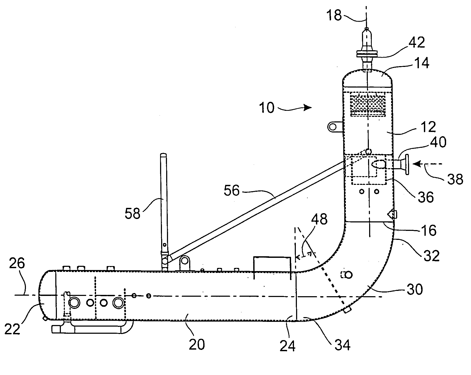
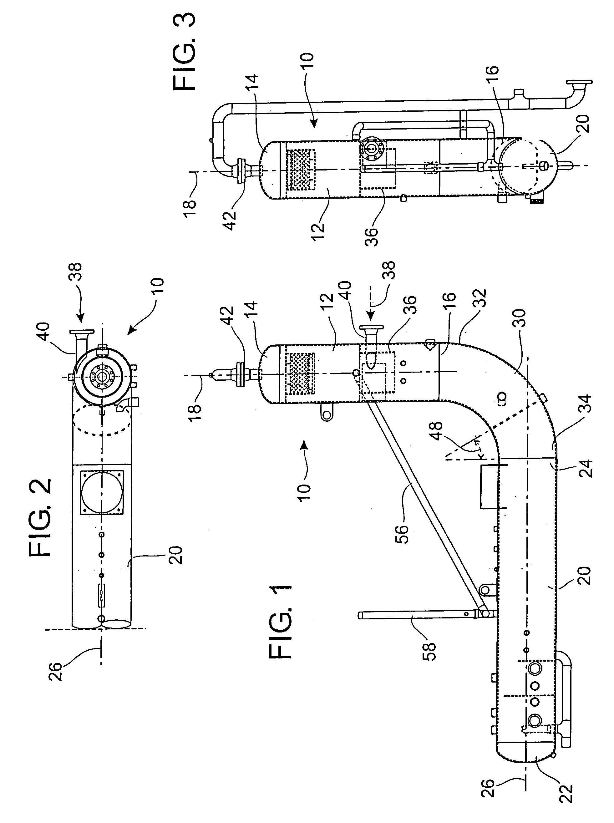
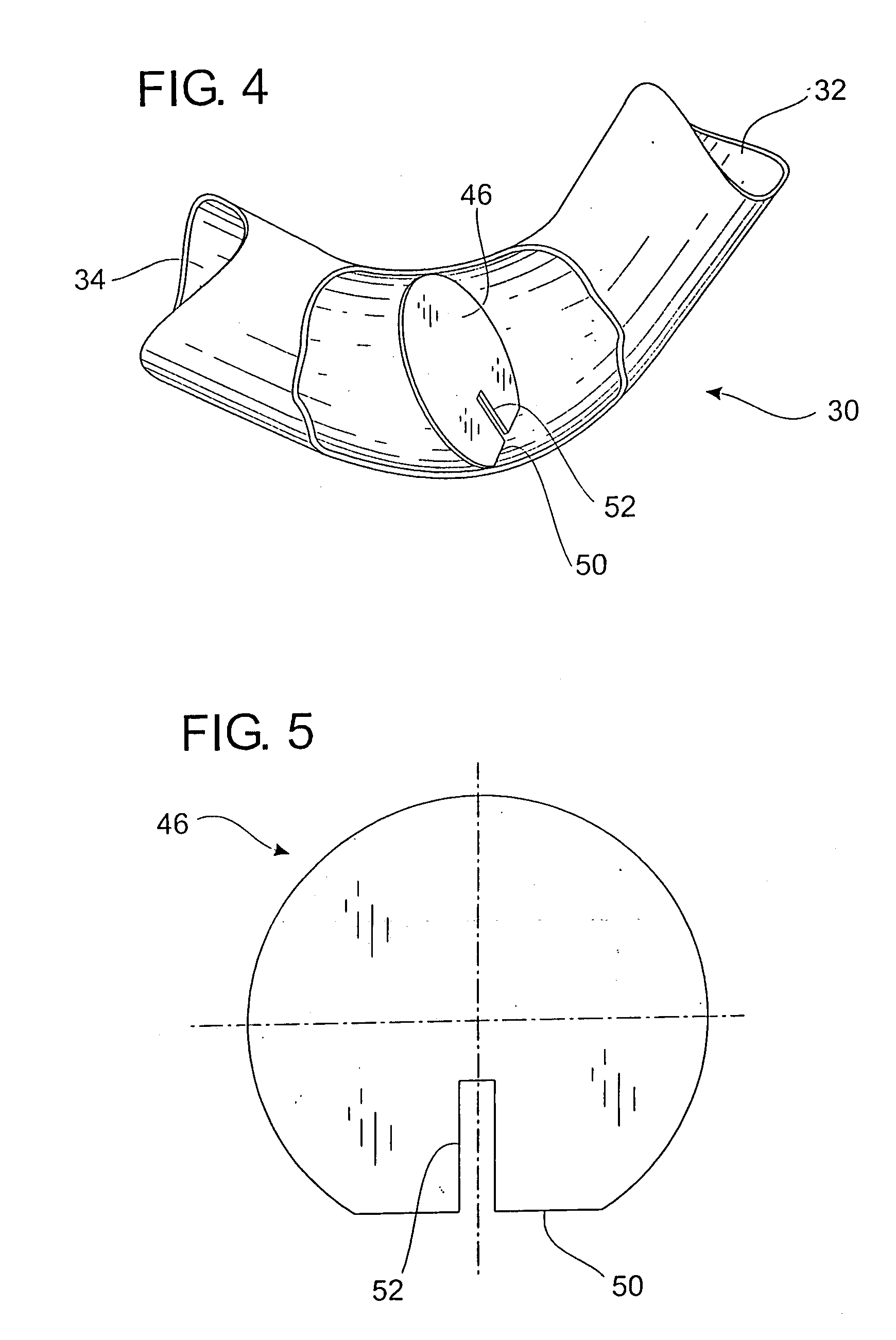
[0028] Referring to the drawings in detail, FIG. 1 illustrates a side view, FIG. 2 is a top view, and FIG. 3 is an end view of an integrated three phase separator 10 for separation of natural gas, hydrocarbon liquid such as oil, and water or brine. The separator 10 includes a cylindrical, vertical separation vessel or unit 12 having a closed top 14 and an open bottom 16. The cylindric...


PUM

PropertyMeasurementUnit
angleaaaaaaaaaa
pressuresaaaaaaaaaa
pressuresaaaaaaaaaa

Abstract

An integrated three phase separator for separation of natural gas, hydrocarbon liquids, and water or brine. The separator includes a cylindrical vertical separation unit having a closed top and an opposed, open bottom. A cylindrical horizontal separation unit has a pair of opposed ends, a first, closed end and a second, open end. A tubular elbow connection includes a pair of ends, one end connected to the open bottom of the vertical separation unit and another end connected to the open end of the horizontal separation unit so that the vertical separation unit and horizontal separation unit are in fluid connection with each other. A metering plate within the tubular elbow connection retains natural gas in the horizontal unit while permitting gentle release of liquid into the horizontal unit.

Description

BACKGROUND OF THE INVENTION [0001] 1. Field of the Invention [0002] The present invention relates to an integrated three phase separator having a vertical separation unit integrated with a horizontal separation unit. [0003] 2. Prior Art [0004] Subterranean oil and gas which is produced from various types of production areas or stratas are intermixed resulting in an emulsion of hydrocarbon liquid such as oil, natural gas and water or brine. Various types of field processing separators have been used in the past to separate the mixture coming from a well head into its constituents of natural gas, hydrocarbon liquid such as oil, and water or brine. [0005] Different types of separator vessels have been used in the past. Horizontal, cylindrical vessels typically have more gas capacity than vertical vessels of the same diameter. Vertical cylindrical vessels have also been used. In general, vertical vessels handle liquid slugs better than horizontal vessels. [0006] In some cases, vessels i...

Claims


Application Information

Patent Timeline
Patent Type & Authority Applications(United States)
IPC IPC(8): B01D17/00E21B43/34
CPCB01D17/00E21B43/34B01D17/005B01D17/0208B01D17/0211B01D17/0217
Inventor RHODES, JAMES E.
Owner PROCESS EQUIP & SERVICE
Learn More