
Multi-functional fireplace

a multi-functional, fireplace technology, applied in the direction of combustion process, domestic heating details, heating fuel, etc., can solve the problems of difficult repair of complex multi-functional fireplaces, and inconvenient use of decorative flames as heat sources, etc., to improve the operative performance of the fireplace

Inactive Publication Date: 2005-04-14
GAZ METRO
View PDF21 Cites 15 Cited by
  • Summary
  • Abstract
  • Description
  • Claims
  • Application Information

AI Technical Summary

Benefits of technology

[0069] In an embodiment, the fireplace further comprises a ventilator for accelerating the flow of air produced by the air conditioner.
[0081] In an embodiment, the ambience burner further produces sufficient heat to be exuded by the fireplace so as to heat a dwelling.
[0126] In an embodiment, the present invention provides the capacity to modulate the burner of the hot air furnace and hence, offer comfort for the user.
[0130] In an alternative embodiment, the burners are so positioned relative to each other in order to achieve the heating burner's effect of minimising the negative effects of the ambiance burner when used as a heating burner.
[0137] In an embodiment of the present invention, heated air distribution can also be used to distribute fresh air in order to replace stale air, which is exhausted from the building. Hence, heat recovery or energy recovery ventilation system, improves the operative performance of the fireplace.

Problems solved by technology

It is difficult to repair complex multifunctional fireplaces since it is not simple for the common owner to gain access to the internal contents of these fireplaces.
While a variety of conventional gas fireplaces can be used for heating, gas fired fireplaces having a rated input of more than 8.5 kW (30,000 BTU / h), have a decorative flame that produces radiant heat which renders the room in which they are installed uncomfortable.
This may be cause for alarm by the dwelling occupant.
Therefore, it is inconvenient to use the decorative flame as a source of heat.

Method used


Image

  • Multi-functional fireplace
  • Multi-functional fireplace
  • Multi-functional fireplace

Examples


Embodiment Construction

[0149] The present invention will be herein described with reference to the appended drawings so as to exemplify the invention and not limit its scope.

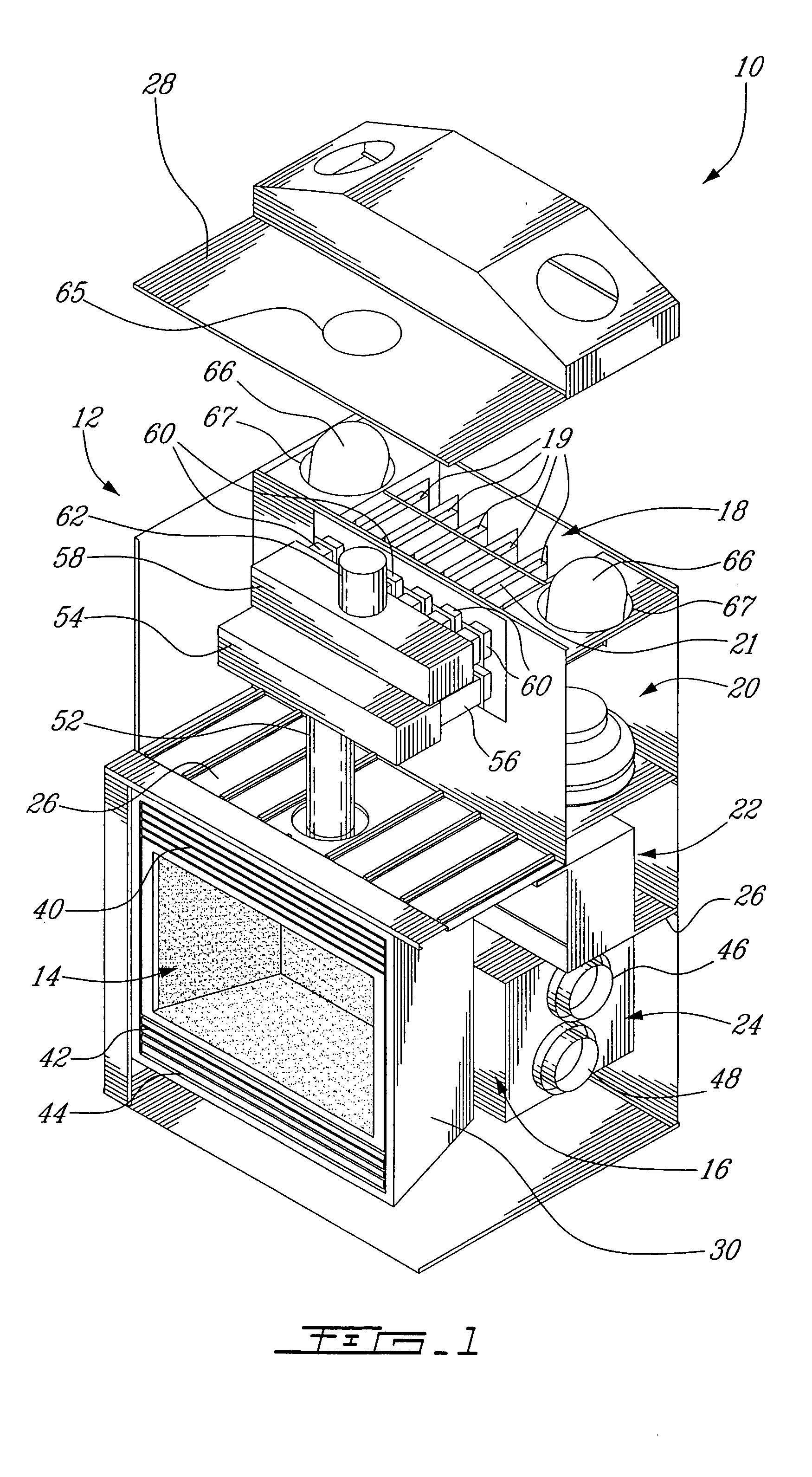
[0150]FIG. 1 shows a fireplace 10 in accordance with an embodiment of the present invention.

[0151] As will be discussed herein fireplace 10 may comprise a multifunctional fireplace including heating and air conditioning capabilities.

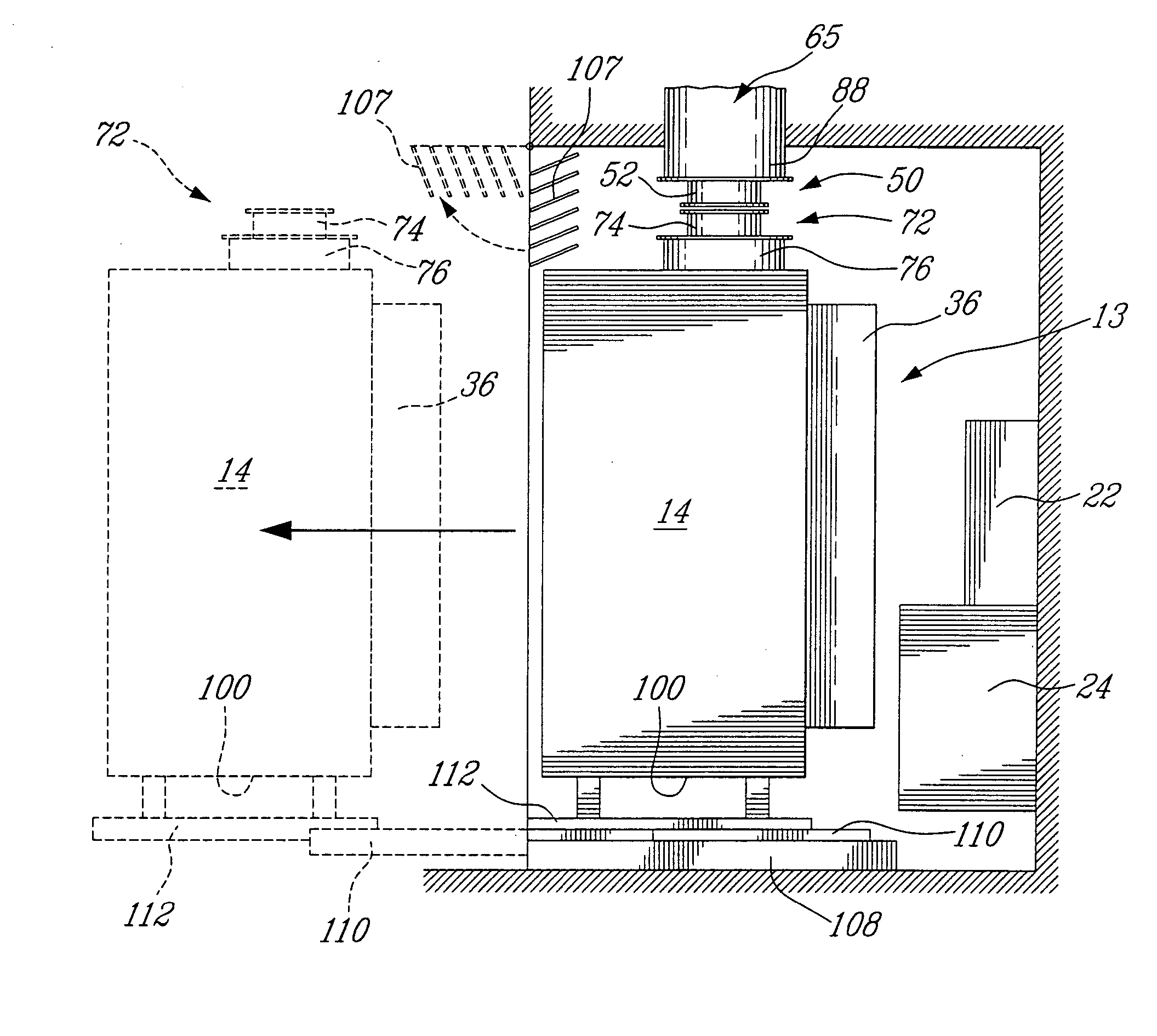
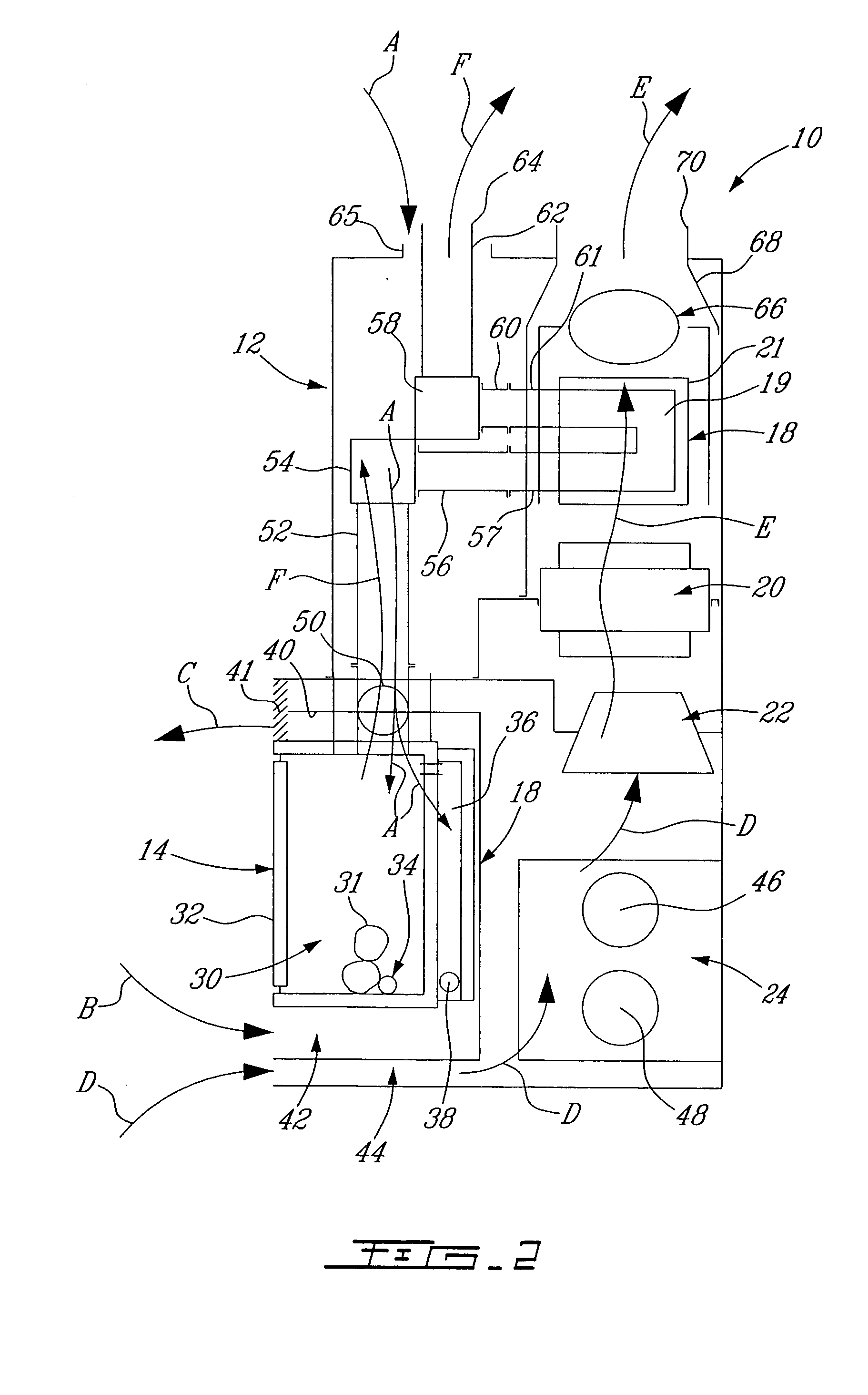
[0152] The fireplace 10 includes a housing 12, which is mountable within a wall structure 13, see FIGS. 2 and 5-8 of a dwelling such as an apartment, condominium or the like. In this way, the front or facade of the fireplace 10 is exposed and the rest of the apparatus is concealed.

[0153] The housing 12 includes compartments for various components, which will be discussed herein.

[0154] As such and with reference to both FIGS. 1 and 2, the fireplace 10 includes a firebox 14, a furnace 16, a heat exchanger 18, a ventilator 20, an air conditioner 22, and an air exchanger / heat recovery unit 24.

[0155] Turn...


PUM


Abstract

A multi-functional fireplace includes a housing for a removable firebox, a multiple burner assembly, a heat exchanger, a ventilator, an air conditioner, and an air exchanger / heat recovery unit. The firebox is removable by various ways from the housing allowing easy access to the internal contents of the fireplace. The multiple burner assembly can be a double burner assembly. One burner is an ambience burner for providing a decorative flame within the firebox and the other burner is the principal heating burner and can be positioned within or outside of the fireplace. A controller may also be linked to the various components of the fireplace to receive data therefrom and for control thereof. A sensor linked to the control can be placed at a heat outlet in order for the controller to detect temperature and accelerate the ventilator if need be. A bypass is also used to avoid cool air from the air conditioner from heating up when the decorative flame is lit.

Description

FIELD OF THE INVENTION [0001] The present invention relates to a multi-functional fireplace apparatus. BACKGROUND OF THE INVENTION [0002] Multifunctional fireplaces are known in the art. Such multifunctional fireplaces include both heating and air conditioning apparatuses. [0003] It is difficult to repair complex multifunctional fireplaces since it is not simple for the common owner to gain access to the internal contents of these fireplaces. [0004] Gas fireplaces are also well known in the art. [0005] While a variety of conventional gas fireplaces can be used for heating, gas fired fireplaces having a rated input of more than 8.5 kW (30,000 BTU / h), have a decorative flame that produces radiant heat which renders the room in which they are installed uncomfortable. As such, it is preferable to limit these fireplaces to less than 7.0 kW (25,000 BTU / h). [0006] Moreover, since the decorative flame of the fireplace is visible, when operated as a heat source, the fireplace's flame appears...

Claims


Application Information

Patent Timeline
Patent Type & Authority Applications(United States)
IPC IPC(8): F24B1/18F24B1/185F24B1/187F24C3/00F24C3/08F24C3/12F24C15/30F24D15/00F24F1/02F24F5/00
CPCF24B1/1808F24C3/122F24B1/187
Inventor BRIERE, LUC
Owner GAZ METRO
Learn More