
Quick-clip sensor holder

a sensor and quick-clip technology, applied in the field of quick-clip sensor holders, can solve the problems of sensor failure, sensor held too tightly to the tissue, interference with physiological parameters, etc., and achieve the effect of avoiding excessive vasoconstriction and reliability of attachment to the patien

Inactive Publication Date: 2005-04-07
DATEX OHMEDA
View PDF12 Cites 168 Cited by
  • Summary
  • Abstract
  • Description
  • Claims
  • Application Information

AI Technical Summary

Benefits of technology

[0006] In view of the foregoing, a primary objective of the present invention is to provide a sensor holder that securely and reliably attaches to a patient's appendage while avoiding excessive vasoconstriction.
[0007] Another objective of the present invention is to provide a sensor holder that accommodates an expanded range in patient appendage sizes.
[0008] A further objective of the present invention is to provide a sensor holder that has a reduced part count.

Problems solved by technology

Holding the sensors too loosely relative to the tissue may result in erroneous readings or sensor failure.
In contrast, sensors held too tightly to the tissue may interfere with the physiological parameter(s) they are supposed to monitor.
As a result, these clip-type sensors tend to readily fall off patient appendages.
Furthermore, the use of a clip-type sensor holder may be limited to a narrow range of appendage sizes.
For example, a small finger may not displace the spring sufficiently to maintain the clip on the finger while a larger finger may displace the spring such that excessive force is applied to the finger.

Method used


Image

  • Quick-clip sensor holder
  • Quick-clip sensor holder
  • Quick-clip sensor holder

Examples


Embodiment Construction

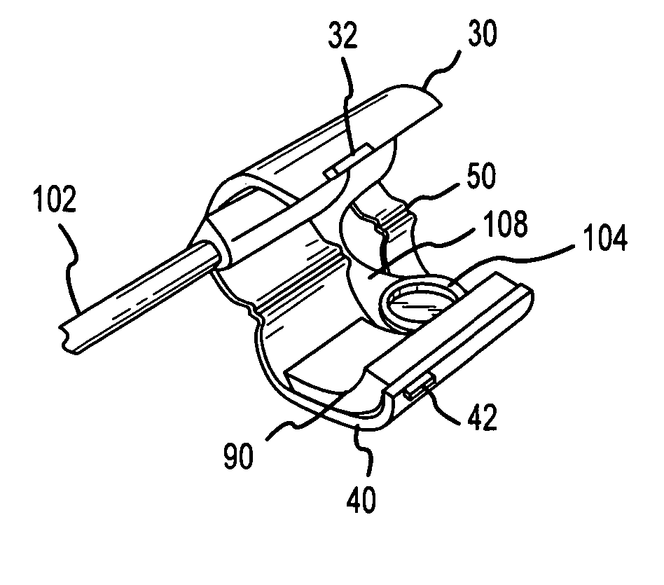
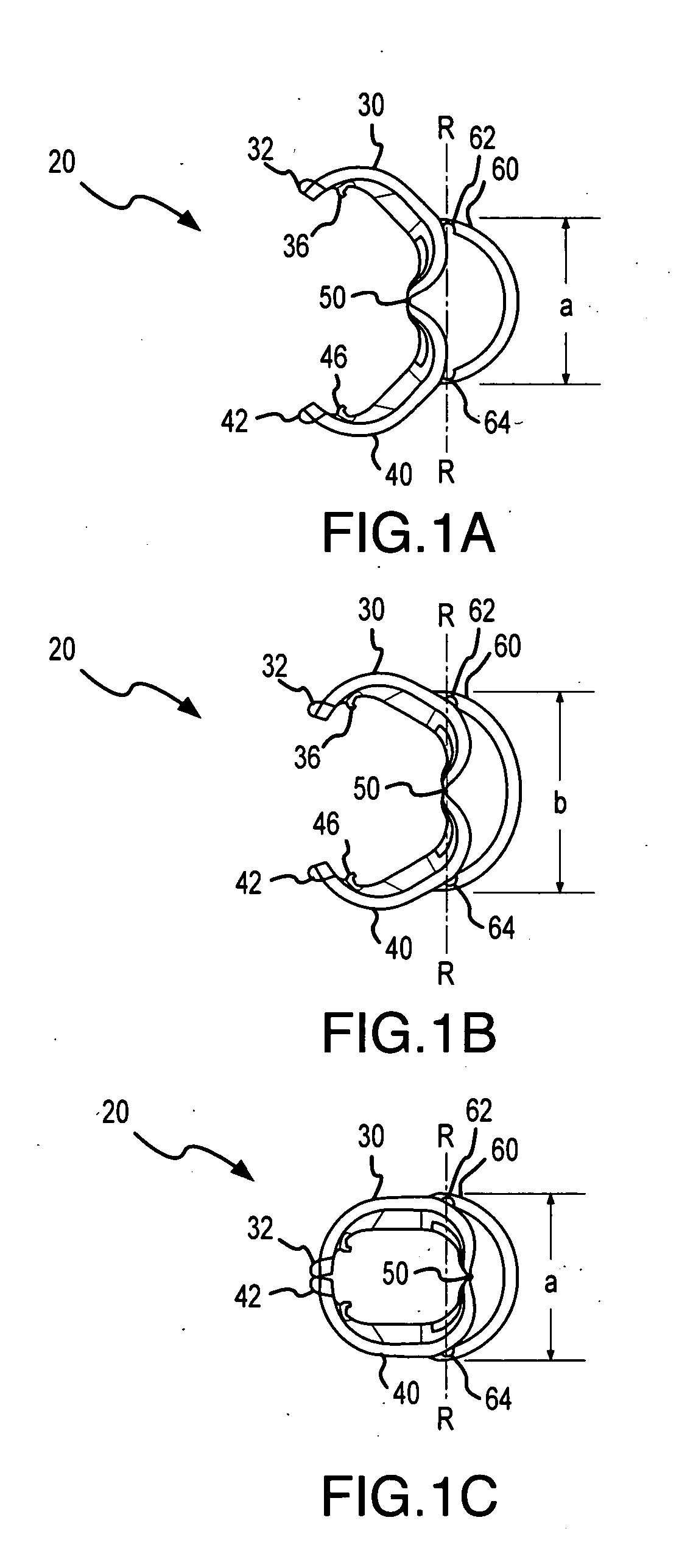
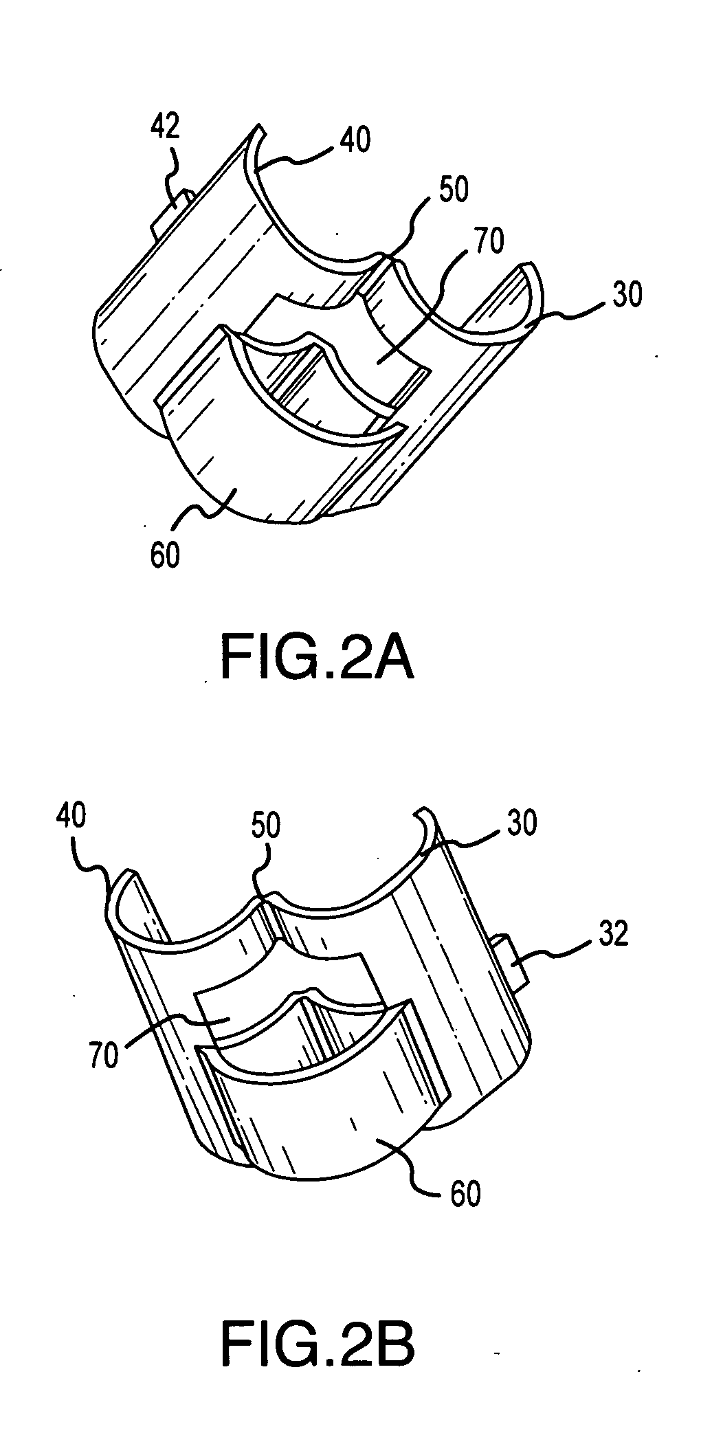
[0030] The present invention will now be described in relation to the accompanying illustrations, which at least assist in illustrating its various pertinent features. The present invention, a sensor holder that clips onto a patient appendage (e.g., finger) is described in conjunction with a pulse oximetry sensor. In particular, the sensor holder is adapted to hold a pulse oximetry sensor having emitters and detectors that are separated such that an optical path is created through patient tissue. However, it will be appreciated that the clip-type sensor holder of the present invention may be utilized with differently configured pulse oximetry sensors as well as other non-invasive medical sensors. In the following description, the invention is set forth in context of an integrally formed sensor holder that utilizes a living hinge member and an “over snap” spring design. This over-snap spring design utilizes a substantially non-biased spring to hold opposing appendage engaging members...


PUM


Abstract

The present invention provides a clip-type medical sensor holder for use in positioning a pulse oximetry sensor relative to a patient appendage. In particular, a clip-type sensor holder is provided that clips around a portion of a patient appendage without necessarily applying a clamping force to that appendage to reduce or eliminate vasoconstrication. The sensor holder includes first and second opposing members in an opposing and hinged relationship that allows these members to move from an open position to a closed position relative to one another. When in the closed position, these opposing members are sized to receive a patient appendage (e.g., a finger) therebetween. A resilient member interconnected to each of the members maintains the sensor holder in the closed position about the patient appendage. In one embodiment, the sensor clip is formed as a one-piece unit allowing simplified construction and a reduced part count.

Description

FIELD OF THE INVENTION [0001] The present invention is generally directed to a holder for positioning a medical sensor relative to patient tissue. More specifically, the present invention is directed to a clip-type sensor holder for use in positioning a pulse oximetry sensor relative to a patient appendage. BACKGROUND [0002] In many medical applications it is desirable to hold one or more sensors in contact with a patient's tissue such that various non-invasive measurements of physiological parameters may be made. For example, a common technique used to monitor blood analyte concentrations and blood oxygen levels is pulse oximetry. In this regard, it is known that the light transmissivity and color of blood is a function of the oxygen saturation of the heme in the blood's hemoglobin. For example, heme saturated with oxygen appears bright red because saturated heme is relatively permeable to red light. In contrast, deoxygenated heme appears dark and bluish, as it is less permeable to...

Claims


Application Information

Patent Timeline
Patent Type & Authority Applications(United States)
IPC IPC(8): A61B5/00
CPCA61B2562/146A61B5/14552
Inventor LINDEKUGEL, ERIC W.
Owner DATEX OHMEDA
Learn More