
Decorative luminaires

a technology luminaires, which is applied in the field can solve the problems that the variety of decorative downlighting luminaires available in the marketplace has not fully addressed user needs

Inactive Publication Date: 2005-04-07
ABL IP HLDG
View PDF3 Cites 37 Cited by
  • Summary
  • Abstract
  • Description
  • Claims
  • Application Information

AI Technical Summary

Benefits of technology

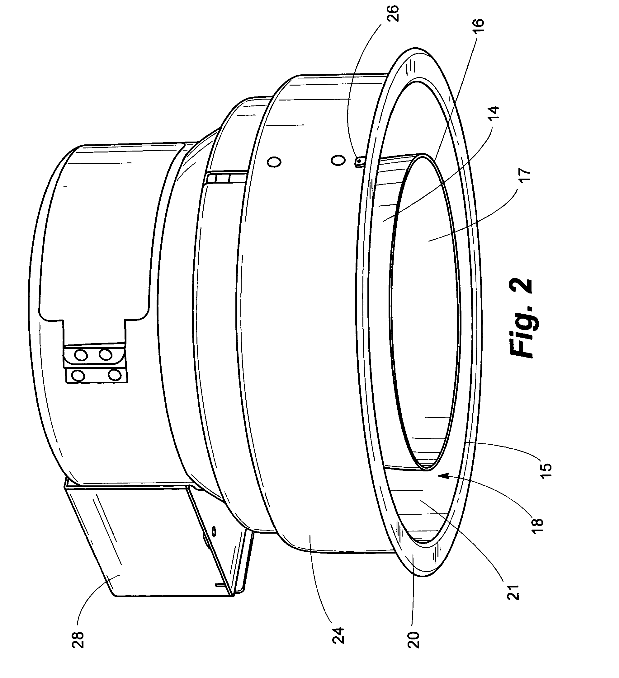
[0010] In a particular embodiment of the invention, the inner reflector is configured with a cylindrical sleeve fitting over a cylindrical innermost portion of said inner reflector, the sleeve having annular corrugations formed on outer surfaces thereof. The corrugations function with an annular O-ring to position the inner reflector at differing locations within the luminaire, outermost edges of the inner reflector being positionable, for example, flushly within the aperture of the luminaire or extending from said luminaire aperture at varying distances to provide an additional decorative function.
[0012] Accordingly, it is an object of the invention to provide decorative luminaires capable of producing illumination of different character from different portions of an aperture of one of said luminaires, a central beam of light emanating from said luminaire typically providing a controlled distribution for usual lighting functions such as general lighting, accent lighting or the like, a second portion of that light emanating from said luminaire being characterized by differing visible properties such as differing coloration from the first-mentioned light, the second portion of the light typically being of a diffuse nature, thereby to provide a luminaire that functions to produce contrasting illumination of decorative appearance.

Problems solved by technology

The variety of decorative downlighting luminaires available in the marketplace has not fully addressed user needs especially as to desired abilities to draw attention to specific areas within a space in a dramatic manner and for tying of illumination to architectural elements of a space.

Method used


Image

  • Decorative luminaires
  • Decorative luminaires
  • Decorative luminaires

Examples


Embodiment Construction

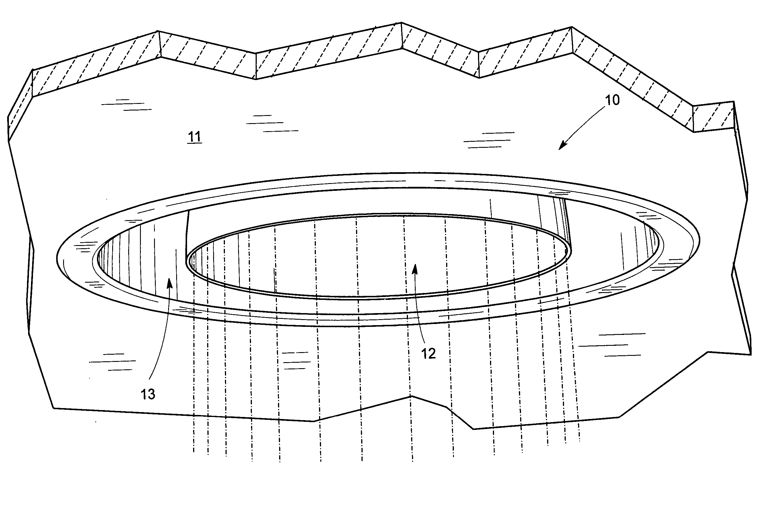
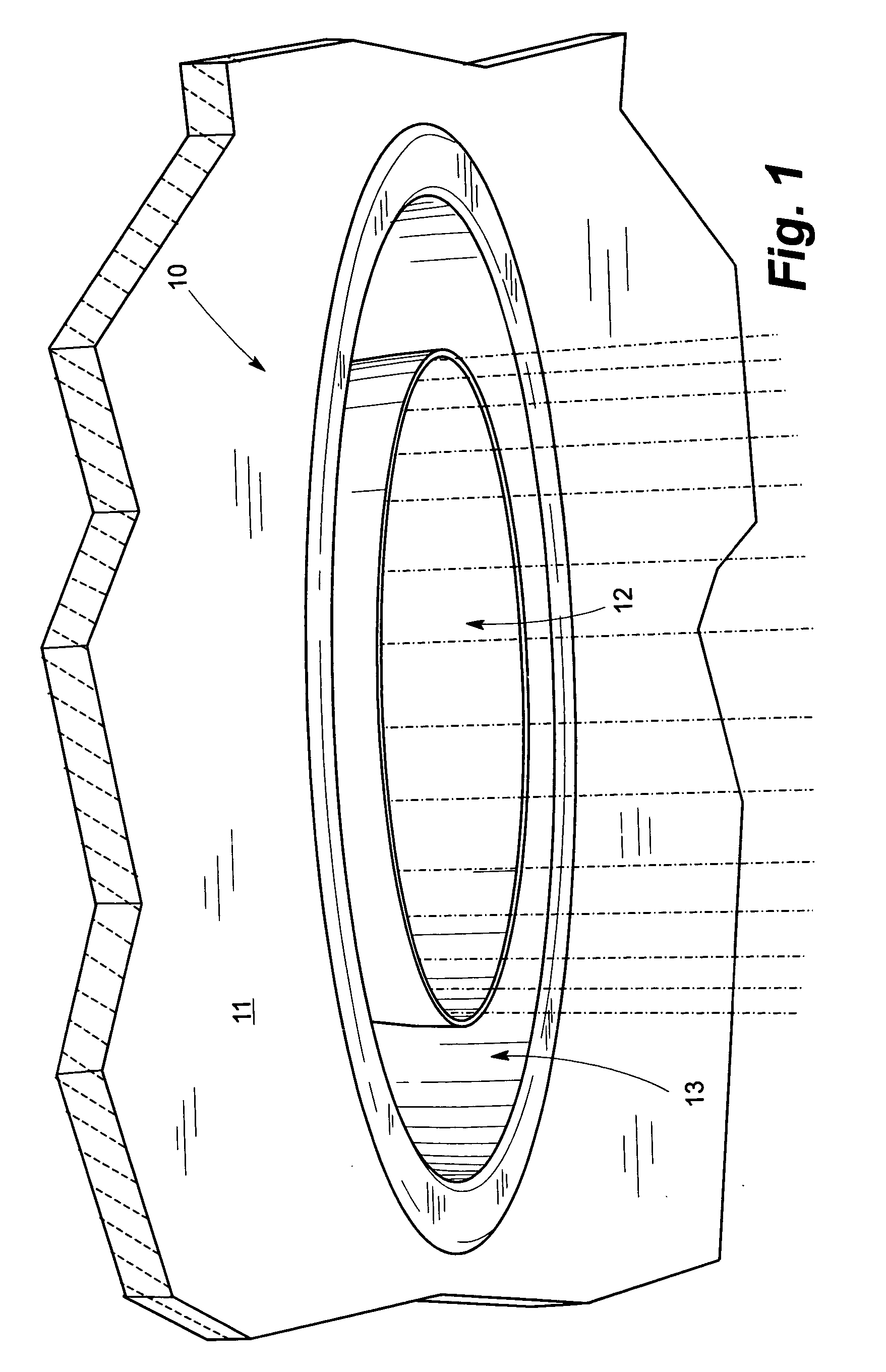
[0038] Referring now to the drawings and particularly to FIG. 1, portions of a decorative downlight luminaire seen generally at 10 are mounted substantially flushly with a ceiling 11, the luminaire 10 directing an illuminating beam 12 from central portions thereof, the beam 12 preferably being white light intended to provide illuminating functions such as general lighting, task lighting, accent lighting and the like within an environmental space within which the luminaire 10 is mounted. As noted by the appearance of the illumination provided by the luminaire 10, the beam 12 is seen to be surrounded by an annulus of light generally seen at 13, the annulus 13 of light essentially surrounding the beam 12 as shown. The overall appearance and affect of the illumination provided by the luminaire 10 being that of a surreal glow reminiscent of impressionistic art and even art deco in its affect on observers thereof. The beam 12 of preferably white light appears in an actual installation of ...


PUM


Abstract

Functional yet decorative luminaires intended to create distinctive environments within specific areas of a space in which one or more luminaires are used, the luminaires of the invention visually tie to architectural elements of the space by providing a customizable glow of color surrounding a typically white light that acts to illuminate the space functionally. A downlighting luminaire configured according to the invention as one example is typically configured to utilize two separate reflectors, usually reflectors having concave reflective surfaces and being mounted concentrically within a housing, an inner reflector directing light centrally through an aperture of the luminaire with the light so directed typically being white light useful for illumination intended to facilitate usual activities within the space. An outer reflector is spaced from the inner reflector with a transparent or translucent disc, such as an acrylic plastic disc, being held between the reflectors, the disc having a colored film adhered preferably to lower surfaces thereof to cause portions of the light emanating from lamping disposed above the disc to be colored by passage through the colored film, the disc being readily removable and replaced with a disc having a different color adhered thereto so that a particular luminaire can be customized as to color selection depending on user choice at any given time. An annulus of glowing, colored light exits the periphery of the luminaire aperture outwardly of the inner cone, the reflective surfaces of the outer reflector directing at least portions of the colored light passing through the disc and colored film through an annular aperture of the luminaire, thereby creating a distinctive appearance of a central, white shaft of light emanating from the inner reflector and a glowing annulus of colored light surrounding the white shaft of light. Peripheral edges of the inner reflector can be positioned flushly with the luminaire aperture or can extend to one or more positions outwardly of the luminaire aperture and thus “proud” of a ceiling or the like within which the luminaire is recessed, surface-mounted or pendently mounted inter alia.

Description

BACKGROUND OF THE INVENTION [0001] 1. Field of the Invention [0002] The invention relates generally to luminaires such as downlighting and / or pendently-mounted luminaires and particularly to such luminaires having multiple reflectors arranged such that light reflected through a luminaire aperture by at least one of the reflectors is colored to produce a dramatic appearance. [0003] 2. Description of the Prior Art [0004] The use of downlighting has expanded in recent years due in part to a flexibility of use of the wide variety of available downlighting luminaires as well as the ability to apply downlighting in a variety of environments requiring either general lighting, task lighting, accent lighting and the like including combinations thereof. The very nature of downlighting permits the luminaires employed to be relatively unobtrusive since downlighting luminaires are typically recessed in a ceiling or the like. However, downlighting luminaires can provide a decorative function in a...

Claims


Application Information

Patent Timeline
IPC IPC(8): F21S8/00F21S8/02F21V7/00F21V9/08F21V17/16
CPCF21S8/02F21S8/026F21V7/0025F21V9/08F21V13/08Y10S362/80F21Y2101/02F21Y2103/025F21Y2113/00F21Y2113/02F21V17/168F21Y2103/37F21Y2113/20F21Y2115/10
Inventor KING, LESLIE CHARLESGOULD, CARL T.VIER, CHESTER G.
Owner ABL IP HLDG
Learn More