Loader implement

a technology of loader implements and supports, which is applied in the directions of transportation and packaging, pedestrian/occupant safety arrangements, vehicular safety arrangements, etc., can solve the problems of operator failure the height of the loader implement may be an obstacle, and the operator of the vehicle may fail to erect the roll-bar, so as to reduce the height of the loader implements and improve the stability of the protective assembly or the roll-bar

Inactive Publication Date: 2005-04-07
DEERE & CO
View PDF18 Cites 26 Cited by
  • Summary
  • Abstract
  • Description
  • Claims
  • Application Information

AI Technical Summary

Benefits of technology

[0008] If the loader implement is operated without a loader arrangement, there should appropriately be a guarantee that the protective assembly can be pivoted into the non-protective position. For this purpose, a retaining arrangement or an anchoring arrangement can be provided for the protective assembly between an operator's platform of the loader implement and the support mast. Preferably, the support mast for the loader arrangement is attached at the side of the loader implement. Moreover, an arrangement of the retaining arrangement for the protective assembly between the flank of the loader implement and the support mast is also possible, so that the roll-over protective device is arranged to pivot o the inner side of the support mast. Further more, it is also conceivable to fasten the protective assembly directly to the support mast for the loader arrangement and thereby to configure the retaining arrangement or anchoring arrangement of the roll-over protective assembly and the support mast as a combined component. The protective assembly can be connected in joints, free to pivot, by means of a hinge or a pin to the support mast in such a way that, during the pivoting, the protective assembly does not collide with any part of the support mast. A pivoting of the protective assembly into the non-protective position is appropriate at the time when the least possible height of the loader implement is required in order to avoid any damage, for example, to branches projecting into the path of movement of the protective assembly during operation in fruit orchards.
[0009] Preferably a locking arrangement is provided with which the protective assembly can be locked in the protective position or the non-protective position. The locking can be accomplished by means of a spring pin or spring bolt that extends through components of the protective assembly and a corresponding bore of the retaining arrangement or the anchoring arrangement in a pivot region of the protective assembly. It is also conceivable to provide the support mast with corresponding bores for the locking in the pivoting region of the protective assembly, so that the protective assembly can be locked in the protective position or the non-protective position. The locking avoids unintended pivoting movements or vibrations, and the protective assembly can be firmly retained in the protective position whether the loader arrangement is mounted or not mounted.
[0012] Preferably, the second section of the protective assembly generally follows the contour of the surface of the hood, so that the protective assembly can ideally be laid around the hood without blocking the view of the operator.
[0014] In a further embodiment, the protective assembly and / or the roll-bar can be constructed so as to permit selected infinite adjustment, or step-wise adjustment in its length or height. This can be attained, for example, by a telescopic arrangement of the components of the protective assembly and / or of the roll-bar and can be locked in their effective length as a function of demand. The locking can be performed, for example, by means of pins that are inserted into correspondingly spaced bores. Tensioning devices are also conceivable here in the form of adjusting screws with which the components can be tensioned with respect to each other. A step-wise change in the effective length has the advantage that the protective function of the protective assembly or the roll-bar need not be omitted, if only a minor reduction in the height of the loader implement is required. Then the protective assembly or the roll-bar need not be brought into the non-protective position so that a protective assembly or roll-bar remains installed for the subsequent protection of the implement operator, although to a reduced extent.
[0015] Preferably the protective assembly can be combined with the roll-bar in the protective position. This makes it possible for the protective assembly, in conjunction with the roll-bar, to form a protective cage around the implement operator or around the operator's platform. Thereby the stability of the protective assembly or of the roll-bar is simultaneously improved. For this purpose, the horizontal second section of the protective assembly is rigidly connected to the roll-bar by fasteners in a manner permitting the protective assembly to be selectively released from the roll-bar. It is also conceivable that only the roll-bar, or both the protective assembly and the roll-bar, are provided with an upper section that extends horizontally over the operator's platform. In the latter case, the respective upper sections of the protective assembly and the roll-bar can be releasably connected to each other.

Problems solved by technology

For operations in narrow or low space, the roll-bar may be an obstacle.
The problem here is that during the installation of the loader arrangement, the pivoted roll-bar can remain in a horizontal position, so that an operator of the vehicle could fail to erect the roll-bar.
However, without the roll-bar the safety of the operator is impaired.

Method used


Image

  • Loader implement
  • Loader implement
  • Loader implement

Examples


Embodiment Construction

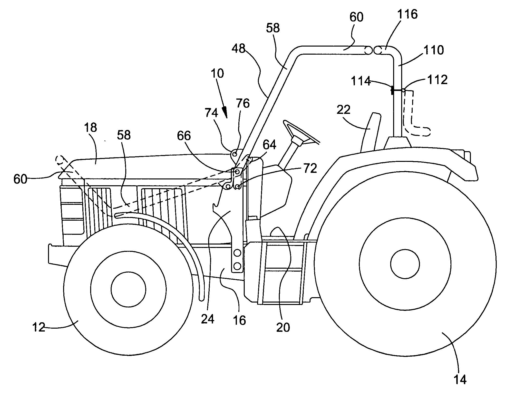
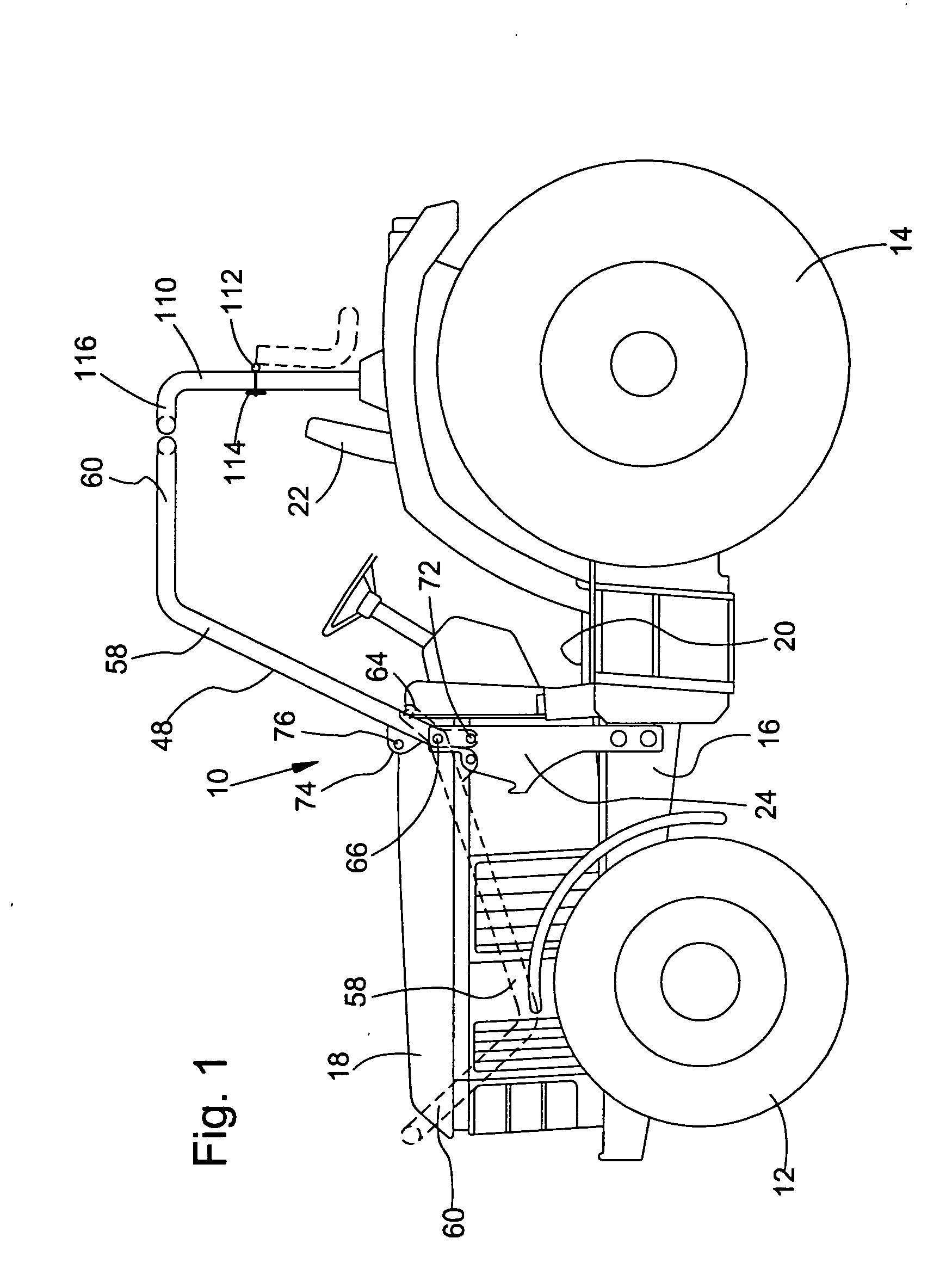
[0023]FIGS. 1-3 show a loader implement 10 constructed in accordance with the principles of the invention. In the embodiment shown, an agricultural tractor is depicted as the loader implement 10. Other loader implements would also be appropriate, such as, for example, small tractors, forestry vehicles, construction vehicles or the like. The loader implement 10 is provided with front and rear wheels 12 and 14, respectively, that are connected to a frame 16 of the loader implement 10. A hood 18 is arranged on a front region of the loader implement 10 above the frame 16. Between the wheels 12 and 14 of the loader implement 10, an operator's platform 20 follows above the frame 16 with an implement operator's seat 22. On either side of the hood 18, the loader implement 10 includes support masts 24 that are used to support a loader arrangement 26, as is shown in FIG. 2.

[0024] The support mast 24 is shown in greater detail in FIGS. 4 and 5. The support mast 24 is comprised generally of a ...


PUM


Abstract

The entire right, title and interest in and to this application and all subject matter disclosed and / or claimed therein, including any and all divisions, continuations, reissues, etc., thereof are, effective as of the date of execution of this application, assigned, transferred, sold and set over by the applicant(s) named herein to Deere & Company, a Delaware corporation having offices at Moline, Ill. 61265, U.S.A., together with all rights to file, and to claim priorities in connection with, corresponding patent applications in any and all foreign countries in the name of Deere & Company or otherwise.

Description

FIELD OF THE INVENTION [0001] A loader implement includes a support mast provided with a mounting area for a loader arrangement, in particular for a front loader, and for at least part of a roll-over protective frame assembly, that can be brought into a protective position and a non-protective position. Furthermore, the invention concerns a support mast of a loader arrangement. BACKGROUND OF THE INVENTION [0002] In the state of the art, agricultural vehicles such as tractors are known with which loader operations can be performed by means of a loader arrangement, for example, a front loader. Loader operations can include stacking operations, but also planning operations, shove operations or clearing operations. In part such vehicles are offered for sale without an operator's cab, in particular in the case of smaller vehicles, for example, small tractors, with which in addition to loader operations other operations can also be performed in narrow spaces and particularly in spaces wit...

Claims


Application Information

Patent Timeline
Patent Type & Authority Applications(United States)
IPC IPC(8): B60R21/13E02F9/16E02F9/24
CPCB60R21/131E02F9/24E02F9/163E02F3/627
Inventor BOUCHER, JEAN-FRANCOIS
Owner DEERE & CO
Why Eureka
Try Eureka