Remote-controlled robot and robot self-position identification method

a robot and self-positioning technology, applied in the field of remote-controlled robots and robot self-position identification methods, can solve the problems of inability to remote-control conventional electrical home appliances that cannot be connected to lans, complex connection between a plurality of cameras and a host computer, and increase in cos

Inactive Publication Date: 2005-03-31
FUJITSU LTD
View PDF7 Cites 51 Cited by
  • Summary
  • Abstract
  • Description
  • Claims
  • Application Information

AI Technical Summary

Benefits of technology

[0010]FIG. 1 shows the basic configuration of the remotely controlled robot of the present invention. A robot 1 comprises a layout storage unit 2, a communication unit 3 and a travel control unit 4.

Problems solved by technology

Furthermore, the connection between a plurality of cameras and a host computer becomes complex and the cost increases, which is a problem.
However, conventional electrical home appliances that cannot be connected to LAN cannot be remote-controlled, which is another problem.
However, it is impossible to attach a characteristic landmark to an average house.
Even if an existing characteristic point can be registered as a landmark, the size of a target on a camera screen varies depending on the position of a robot so the picture cannot easily determine the landmark, which is another problem.

Method used


Image

  • Remote-controlled robot and robot self-position identification method
  • Remote-controlled robot and robot self-position identification method
  • Remote-controlled robot and robot self-position identification method

Examples


Embodiment Construction

[0044]FIG. 2 shows the configuration of the remotely controlled robot in the preferred embodiment.

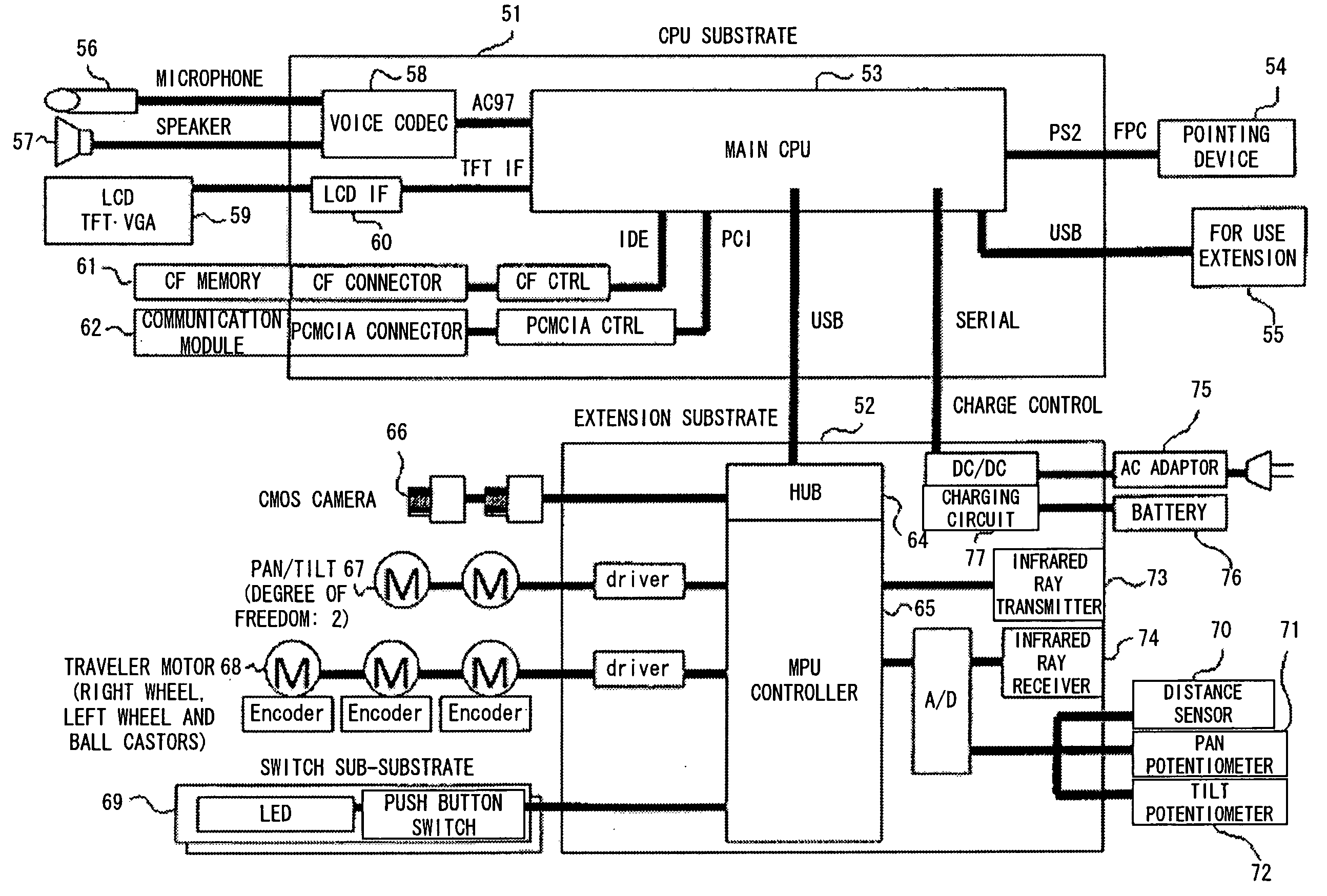
[0045] In FIG. 2, the robot comprises a control computer 10, a travel mechanism 11, a camera 12 taking pictures around the robot, a pan / tilt stand 13 for adjusting the horizontal revolution angle and elevation / depression angle of the camera, an infrared transmitter / receiver 14 that is, for example, mounted on the same base as that of the camera, transmitting infrared rays in parallel to the shooting direction of the camera and receiving infrared rays to get remote control data, a radio communication unit 15, an input device 16, a pointing device 17, a display device 18, a variety of switches 19 and a variety of sensors 20.

[0046] In FIG. 2, the camera 12 is, for example, a video camera. The infrared transmitter / receiver 14 is installed in the vicinity of the camera 12, and can transmit infrared rays in the same direction as the shooting direction. Its base can be revolved in an arbitra...


PUM


Abstract

A remotely controlled robot comprises a unit storing the layout plan of a building, a unit receiving a position remotely designated in the layout plan from a remote location and a unit controlling the travel of the robot to the designated position. A self-position identification method is implemented by a robot with a camera whose shooting direction can be changed. The robot takes in advance a panoramic picture of a room where the robot may travel, generates a reference picture by extracting a plurality of block pictures from the panoramic picture and identifies a room where the robot is located, by applying correlation and DP matching, using both a picture taken in the room where the robot is located and the reference picture.

Description

CROSS REFERENCE TO RELATED APPLICATION [0001] This application is a continuation of international PCT application No. PCT / JP02 / 05370 filed on May 31, 2002.BACKGROUND OF THE INVENTION [0002] 1. Field of the Invention [0003] The present invention relates to a technology for controlling and using a robot. In particular, it relates to a technology for controlling and using a robot, where a robot can be remotely controlled, for example, through the Internet when it is located in a building. It also relates to a robot self-position identification method for recognizing the exact current position and direction of a robot. [0004] 2. Description of the Related Art [0005] Conventionally, an Internet camera has been used to remotely monitor a person's home while he / she is away. However, this Internet camera is fixed in a specific location, and in order to monitor each room of a building, such a camera must be installed in each room. Furthermore, the connection between a plurality of cameras an...

Claims


Application Information

Patent Timeline
Patent Type & Authority Applications(United States)
IPC IPC(8): G01C15/00G01S5/16G05D1/00G05D1/02G06K9/00G06K9/64G06T7/00
CPCG05D1/0038G05D1/0229G05D1/0242G05D1/0251G05D1/0272G06T2207/30244G05D2201/0207G06K9/00664G06T7/0044G06T2200/32G06T2207/20021G05D1/0274G06T7/74G06V20/10G05D1/02
Inventor OKABAYASHI, KEIJUOKABAYASHI, MIWAMURASE, YUICHISHIMIZU, KATSUTOSHIIWASHITA, SUMIHISASAWASAKI, NAOYUKI
Owner FUJITSU LTD
Why Eureka
Try Eureka