
Biopsy device with viewing assembly

a technology of biopsy device and viewing assembly, which is applied in the field of biopsy device having a viewing assembly and an introducer therefor, can solve the problems of mixed cellularity of the specimen obtained, limited therapeutic options and survival rates, and limited imaging techniques

Inactive Publication Date: 2005-03-31
LACHOWICZ THEODORE COLLATERAL AGENT
View PDF8 Cites 36 Cited by
  • Summary
  • Abstract
  • Description
  • Claims
  • Application Information

AI Technical Summary

Benefits of technology

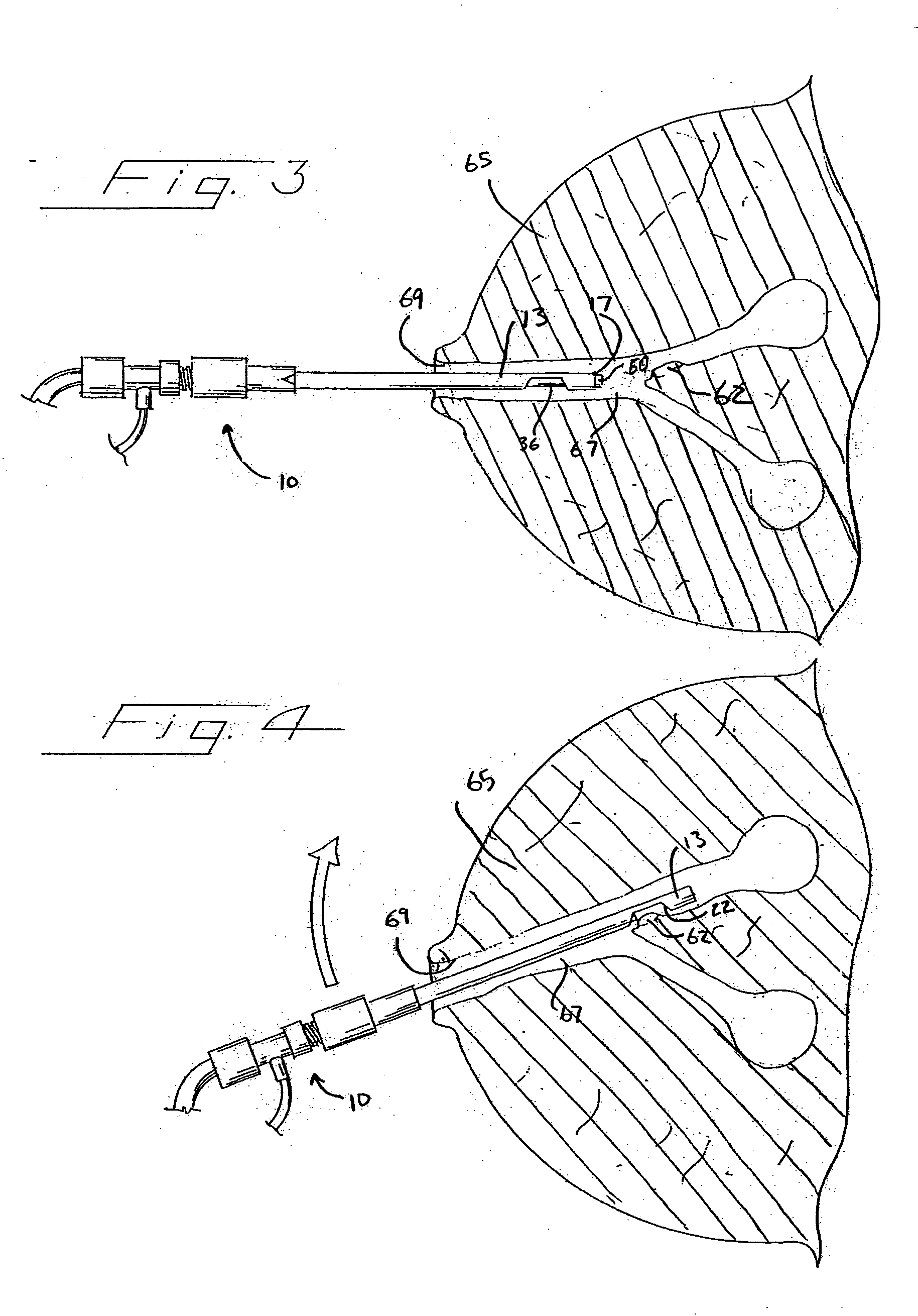
[0010] The cutter sheath and introducer sheath distal end portions are moved relative to one another so as to cause a tissue sample that extends into the biopsy device though the introducer sheath aperture to be scissored or cut from the mammary duct wall. It is not critical to the present device whether the cutter sheath or the introducer sheath is movable as long as relative movement between these two structural components effects cutting of the tissue. In other words, movement of the cutter sheath, the introducer sheath, or a combined movement of the two may cut the tissue. During the cutting process, the viewing end of the endoscope is positionable near the aperture through which the tissue extends such that the cutting procedure may be viewed by a practitioner as it takes place.

Problems solved by technology

One problem with mammography is that such an imaging technique can only find breast cancer once it has taken form.
All too often, breast cancer is discovered at a stage that is too far advanced, when therapeutic options and survival rates are severely limited.
While examination of mammary duct discharge has many benefits, one weakness is the relatively low and mixed cellularity of the specimens obtained.
Such a system significantly decreases the invasiveness of the biopsy procedure by only requiring a small incision and puncture, which may be done under local anesthetic.
However, in certain situations, such as where the tissue to be biopsied is in a mammary duct, the incision and probe insertion required with the Mammotome® is unnecessarily invasive and undesirable.

Method used


Image

  • Biopsy device with viewing assembly
  • Biopsy device with viewing assembly
  • Biopsy device with viewing assembly

Examples


Embodiment Construction

[0023] The invention disclosed herein is susceptible of embodiment in many different forms. Shown in the drawings and described hereinbelow in detail are preferred embodiments of the invention. It is to be understood, however, that the present disclosure is an exemplification of the principles of the invention and does not limit the invention to the illustrated embodiments.

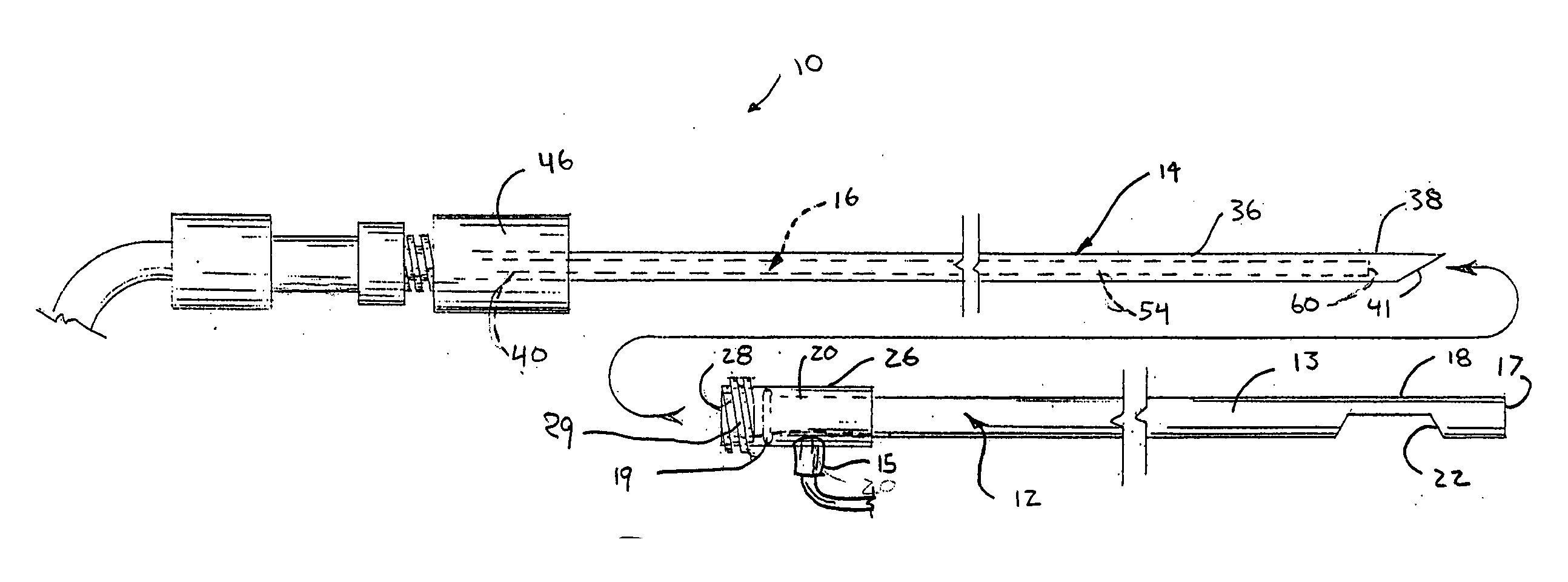
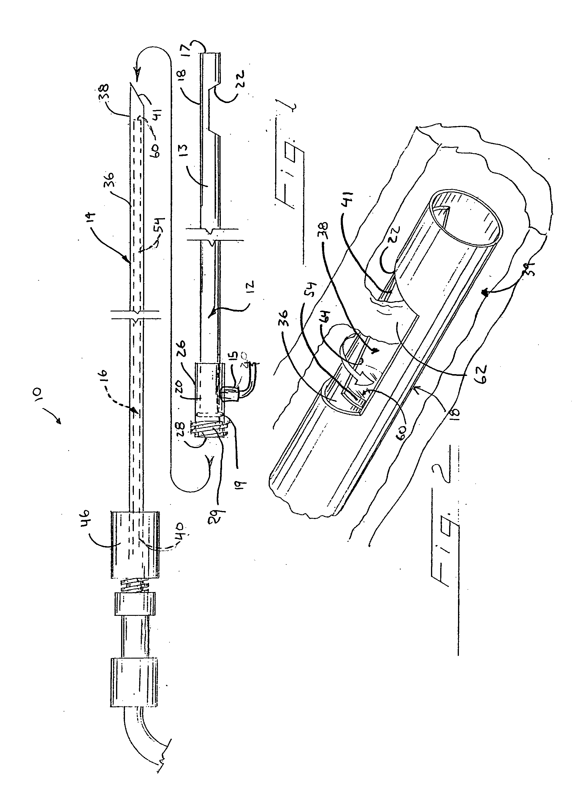
[0024] The biopsy device shown in FIG. 1 represents one preferred embodiment of the present invention. Biopsy device 10 is suitable for collection of a tissue sample from a biopsy site in a body lumen and is comprised of an introducer assembly 12, a cutter assembly 14 receivable within introducer assembly 12, and an endoscope assembly 16 shown in phantom within cutter assembly 14.

[0025] The introducer assembly 12 includes a hollow sheath 13 having a distal end portion 18 and a proximal end portion 20 provided with external threads 29. The sheath distal end portion 18 includes an aperture 22 that is suitable for ...


PUM


Abstract

A biopsy device suitable for collection of a tissue sample from a biopsy site in a body lumen is provided. The biopsy device comprises a combination of an introducer assembly, a cutter assembly, and an endoscope assembly that coact with one another. The introducer assembly includes a hollow sheath having a distal end portion defining an aperture suitable for receiving a tissue mass therein. The cutter assembly includes a cutter tube having a distal end portion with a cutting edge. The cutter tube is sized to fit axially within the introducer sheath. The endoscope assembly includes a bundle of optical fibers sized to fit axially within the cutter tube. In use, the fiber optic bundle of the endoscope is nested within the cutter tube, which in turn is nested within the introducer sheath to form a co-axial structure.

Description

TECHNICAL FIELD OF THE INVENTION [0001] The invention generally relates to a device for obtaining mammary duct tissue samples, such as a papilloma, and the like, for analysis. More specifically, the invention relates to a biopsy device having a viewing assembly and an introducer therefor. BACKGROUND OF THE INVENTION [0002] Breast cancer is one of the health threats most feared by women, and is indeed the most common form of cancer in women. A key to treatment is early detection. For example, an annual mammogram is a method that has been used in hopes of early detection of breast cancer. One problem with mammography is that such an imaging technique can only find breast cancer once it has taken form. All too often, breast cancer is discovered at a stage that is too far advanced, when therapeutic options and survival rates are severely limited. While breast cancer is most common among women, in rare instances the human male may also have occurrences of breast cancer. [0003] Other meth...

Claims


Application Information

Patent Timeline
IPC IPC(8): A61B10/00A61B10/02A61B18/00
CPCA61B2018/00982A61B10/0275
Inventor MUELLER, RICHARD L. JR.
Owner LACHOWICZ THEODORE COLLATERAL AGENT
Learn More