
Vehicular repeater multi-unit system and method for allowing the first vehicular repeater unit on-scene to remain priority

a vehicular repeater and multi-unit technology, applied in the field of priority of vehicular repeaters, can solve problems such as the arrival of fire trucks with vehicular repeaters, the inability of newly arriving vehicular repeaters to be set up correctly on the proper communication channel, and the inability to maintain priority

Inactive Publication Date: 2005-03-31
MOTOROLA INC
View PDF10 Cites 53 Cited by
  • Summary
  • Abstract
  • Description
  • Claims
  • Application Information

AI Technical Summary

Benefits of technology

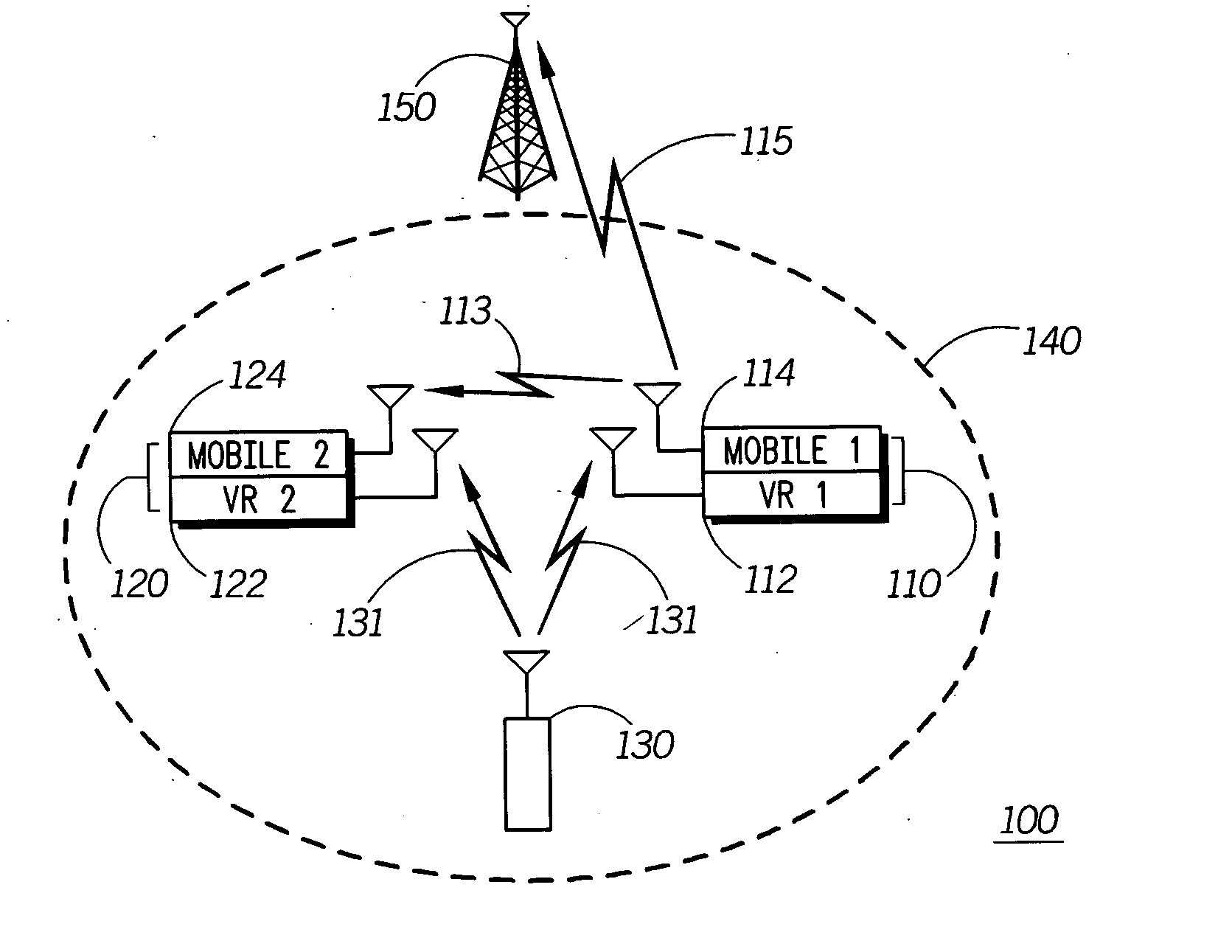
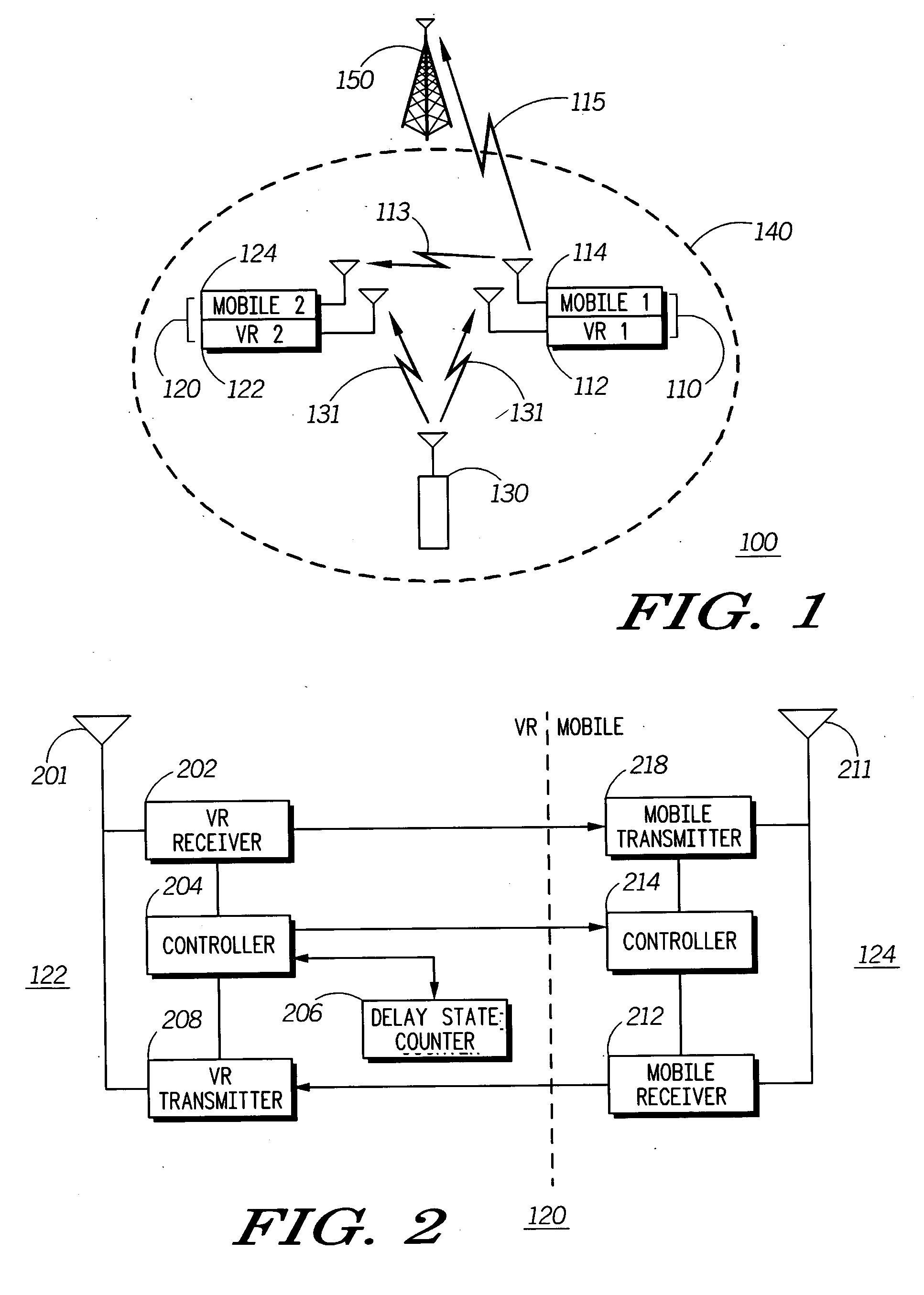
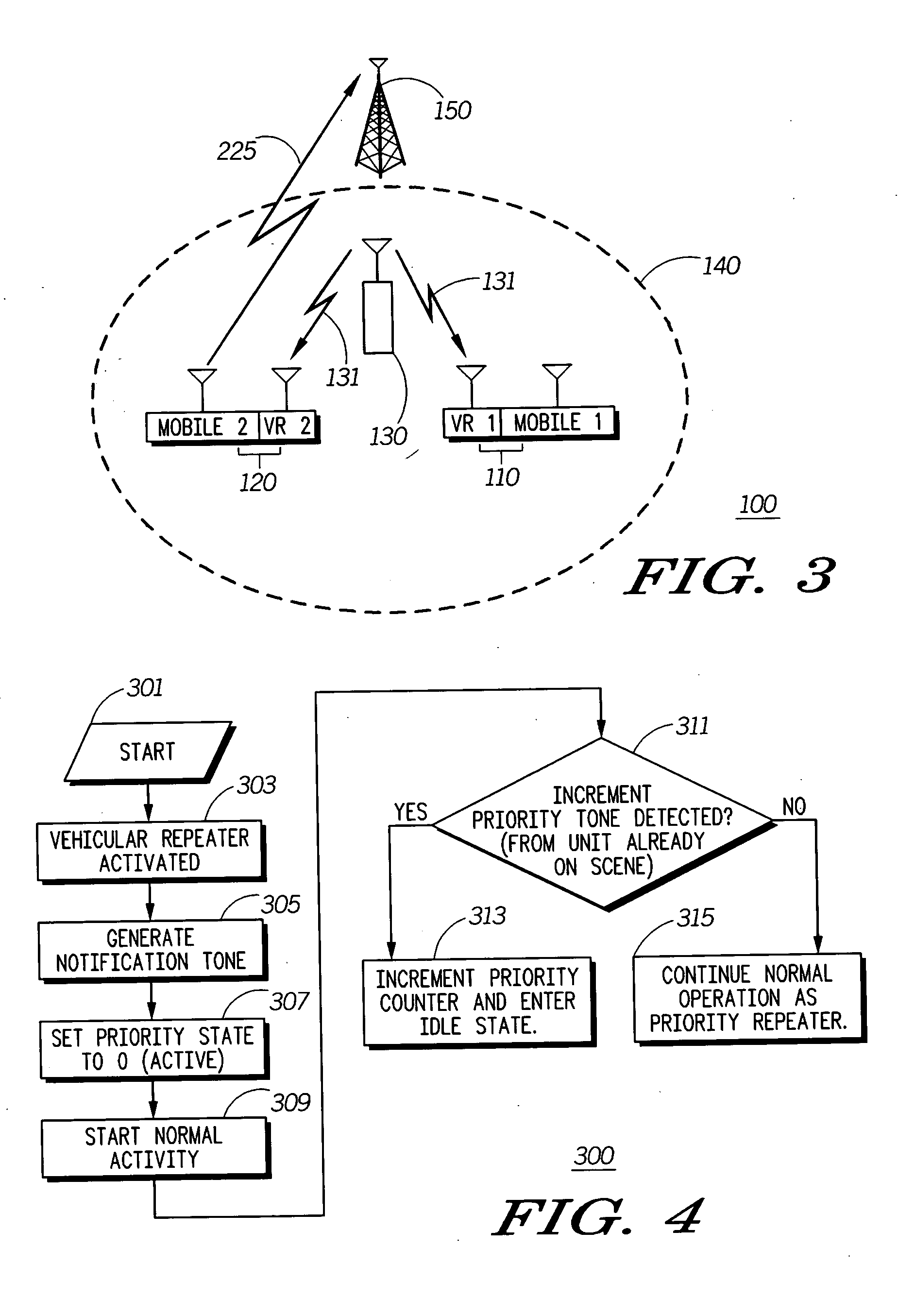
[0004] Briefly, according to the invention, there is provided a vehicular repeater multi-system and method for allowing a first vehicular repeater unit that arrives on-scene to remain as the priority vehicular repeater to other arriving repeaters. In accordance with the invention, after a newly arriving vehicular repeater arrives on-scene, it is activated such that it then transmits an RF notification signal. This notifies other repeaters in the operational area that a new repeater has arrived. It then monitors for receipt of a priority signal from any other vehicular repeaters that may already be in the operational area that wish to remain the priority repeater for that area. If a priority signal is detected, the newly arriving vehicular repeater then moves to an idle and / or non-operational state. If however no priority signal is detected, the newly arriving vehicular repeater assumes control as the primary vehicular repeater for that operational area.

Problems solved by technology

One problem associated with this type of arrangement is in situations where a vehicular repeater is used by a fire department.
It would then be a disadvantage to have subsequent fire trucks with vehicular repeaters arrive at the scene to take control where the repeater in the first truck already has an optimal location.
Moreover, once the repeater is set up on the proper channel, any newly arriving vehicular repeater may not be set up correctly on the proper communications channel.
If the newly arriving unit takes control of the repeated communications, some of the on-going communications could be disrupted since the new repeater may not be set to operate on the communications channel currently being used.

Method used


Image

  • Vehicular repeater multi-unit system and method for allowing the first vehicular repeater unit on-scene to remain priority
  • Vehicular repeater multi-unit system and method for allowing the first vehicular repeater unit on-scene to remain priority
  • Vehicular repeater multi-unit system and method for allowing the first vehicular repeater unit on-scene to remain priority

Examples


Embodiment Construction

[0011] While the specification concludes with claims defining the features of the invention that are regarded as novel, it is believed that the invention will be better understood from a consideration of the following description in conjunction with the drawing figures, in which like reference numerals are carried forward.

[0012] The present invention provides for a vehicular repeater system that supports automatic transitioning from a non-priority mode to a priority mode wherein the first vehicular repeater system on-scene can remain in primary control. Typically, the vehicular repeaters operate in a common communication environment according to a particular priority scheme that designates a priority vehicular repeater and at least one non-priority vehicular repeater. In normal operation, when a vehicular repeater system arrives on-scene and is activated, it will generate a tone to notify any other active vehicular repeater system within this communication environment that it will ...


PUM


Abstract

A communication system (100) including a portable radio (130) selectively transmitting radio signals, a first vehicular repeater system (110) including a first vehicular repeater (112) adaptable to receive radio signals transmitted by the portable radio (130). A first mobile radio (114) is coupled to the first vehicular repeater (112) and is adaptable to retransmit signals received by the first vehicular repeater (112). The first vehicular repeater (112) has priority repeater status that signifies primary responsibility for repeating the radio signals transmitted by the portable radio (130). The first vehicular repeater (112) is also capable of responding to a notification signal received from a second vehicular repeater system (120) with a priority signal to indicate that it is to remain in priority repeater status such that the second vehicular repeater system (120) monitors to receive the priority signal by the first vehicular repeater (112) in order to determine its priority status.

Description

TECHNICAL FIELD [0001] This invention relates in general to two-way, base-mobile portable communications systems and more particularly to the prioritization of vehicular repeaters when two or more vehicular repeaters are in one location. BACKGROUND [0002] Vehicular repeaters are commonly used in public service applications by police, fire and other governmental agencies. As is well known in the art, vehicular repeater systems allow high-power mobile radio units to be used in extending the communications range of portable radio communications units. In operation, a vehicular repeater receives communication signals from a portable radio and retransmits these signals at higher power to enable extended range communication. Preferably, such range extension is automated such that when a portable radio is within communication range of a vehicular repeater this range extension takes place and the portable radio is able to communicate a greater distance. This type of scenario is discussed in...

Claims


Application Information

Patent Timeline
Patent Type & Authority Applications(United States)
IPC IPC(8): H04B7/26
CPCH04W88/04H04B7/2606
Inventor UPTON, MICHAEL P.
Owner MOTOROLA INC
Learn More