
Alarm management system

a technology of alarm management and management system, applied in the direction of testing/monitoring control system, instruments, computing, etc., can solve the problems of inability to secure the appropriate personnel, enormous engineering man-hours, and extremely troublesome work for engineers who face labor-saving staff cuts

Active Publication Date: 2005-03-24
YOKOGAWA ELECTRIC CORP
View PDF4 Cites 19 Cited by
  • Summary
  • Abstract
  • Description
  • Claims
  • Application Information

AI Technical Summary

Benefits of technology

An object of the present invention, therefore, is to provide an alarm management system having the functions to automatically identify and suppress unnecessary alarms.

Problems solved by technology

Then the engineer must identify the causes (for example, incorrect tag ranges) of these alarms and correct them one by one, incurring enormous amounts of engineering man-hours.
This work has been extremely troublesome for engineers who face labor-saving staff cutbacks.
Often, however, it is impossible to secure the appropriate personnel, making it difficult to precisely select unnecessary alarms.

Method used


Image

  • Alarm management system
  • Alarm management system
  • Alarm management system

Examples


Embodiment Construction

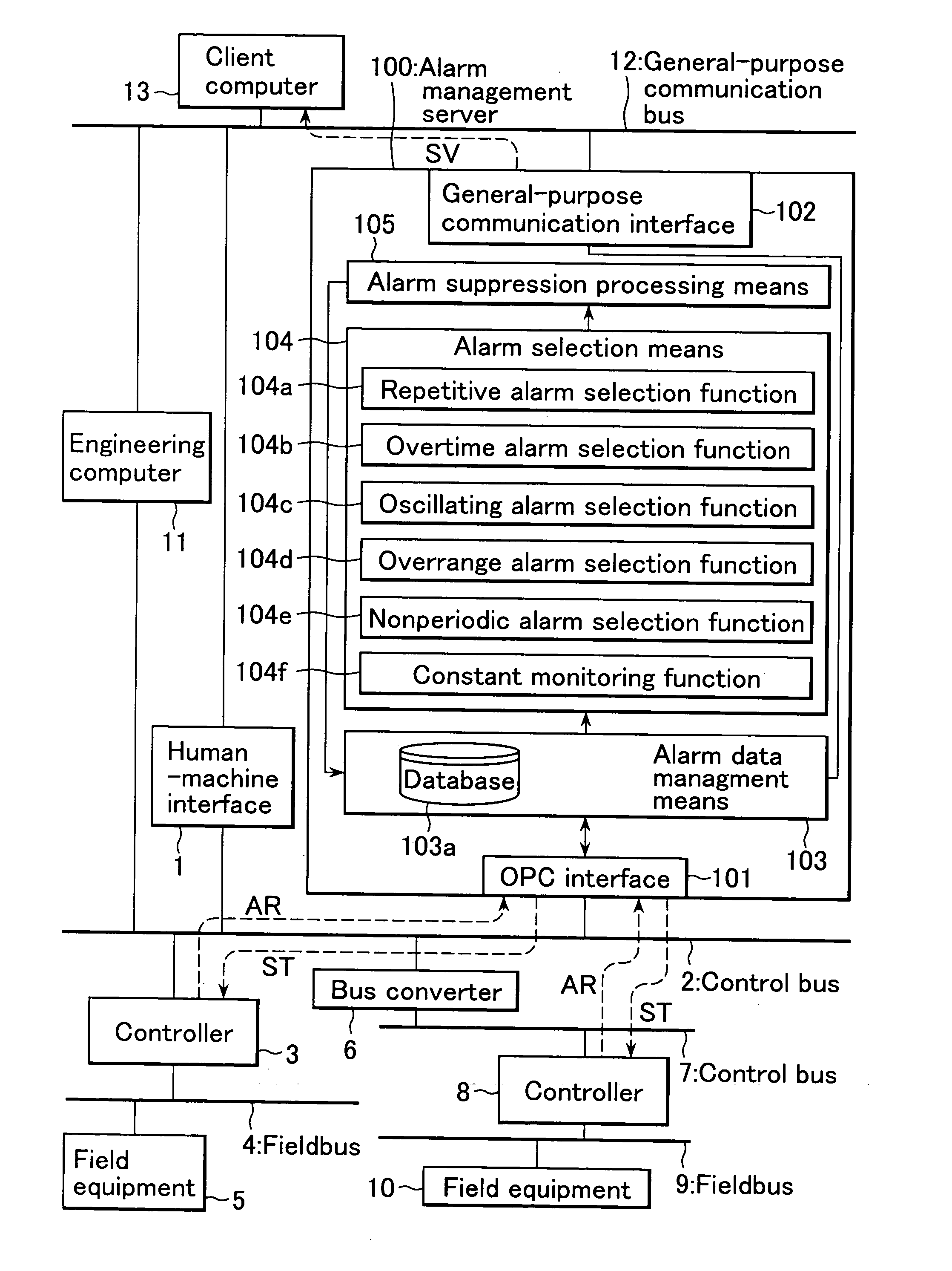
The present invention will now be described in detail with reference to the accompanying drawings. FIG. 2 is a functional block diagram illustrating one embodiment of a hierarchical process control system to which the alarm management system in accordance with the present invention has been applied.

In FIG. 2, numeral 1 denotes a human-machine interface that hosts the hierarchical process control system and is connected to control bus 2. Numeral 3 denotes a controller, which is also connected to control bus 2 to communicate with human-machine interface 1 and with field equipment 5 connected to this fieldbus through fieldbus 4, and controls the field equipment by executing given application programs.

Numeral 6 denotes a bus converter that relays signals between control bus 2 and control bus 7 compliant with a standard different from that of control bus 2. Numeral 8 denotes a controller connected to control bus 7. This controller communicates with human-machine interface 1 through ...


PUM


Abstract

The present invention relates to an alarm management system for acquiring message data for alarms issued from a process and analyzing alarm behaviors. The alarm management system of the present invention selects unnecessary alarms from the message data for alarms and prevents alarms from being issued according to the results of alarm selection. Consequently, the system eliminates the need for engineers who have professional skills and experience, thereby making it possible to precisely select unnecessary alarms.

Description

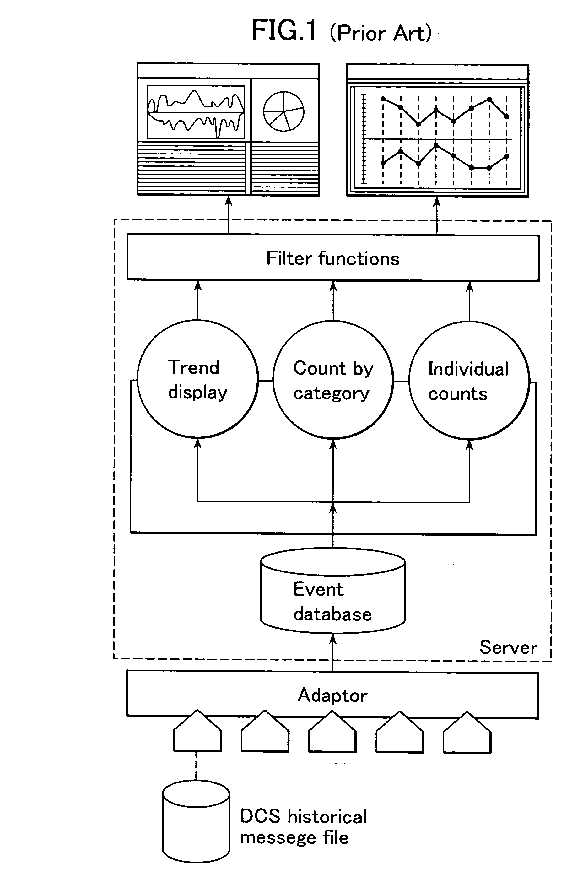
BACKGROUND OF THE INVENTION 1. Field of the Invention The present invention relates to an alarm management system for acquiring message data for alarms issued from a process and analyzing alarm behaviors. 2. Description of the Prior Art Prior art documents related to an event analysis system that acquires and analyzes message data for alarm events, for example, produced from a process include the following. [Non-patent document 1] URL: http: / / www.yokogawa.co.jp / EXASOFT / 13_Exalog / exalog—01.htm Exaplog event analysis package FIG. 1 is a function block diagram illustrating the configuration of an alarm management system disclosed in the GS36J06A10-01 general specifications document downloadable from the web page where non-patent document 1 is placed. The server acquires produced alarm messages (with process data at the moment each message was produced) from the historical message file, which is a log of plant operations kept by the distributed process control system (DCS), and st...

Claims


Application Information

Patent Timeline
IPC IPC(8): G05B23/02G06F3/048G06F3/0484
CPCG05B23/027
Inventor AKAMATSU, NOBUOISHIDA, TAISUKENIINA, NOBUHIROKOBAYASHI, YASUNORI
Owner YOKOGAWA ELECTRIC CORP
Learn More