Vehicle drive system
- Summary
- Abstract
- Description
- Claims
- Application Information
AI Technical Summary
Benefits of technology
Problems solved by technology
Method used
Image
Examples
first embodiment
[0076] First Embodiment
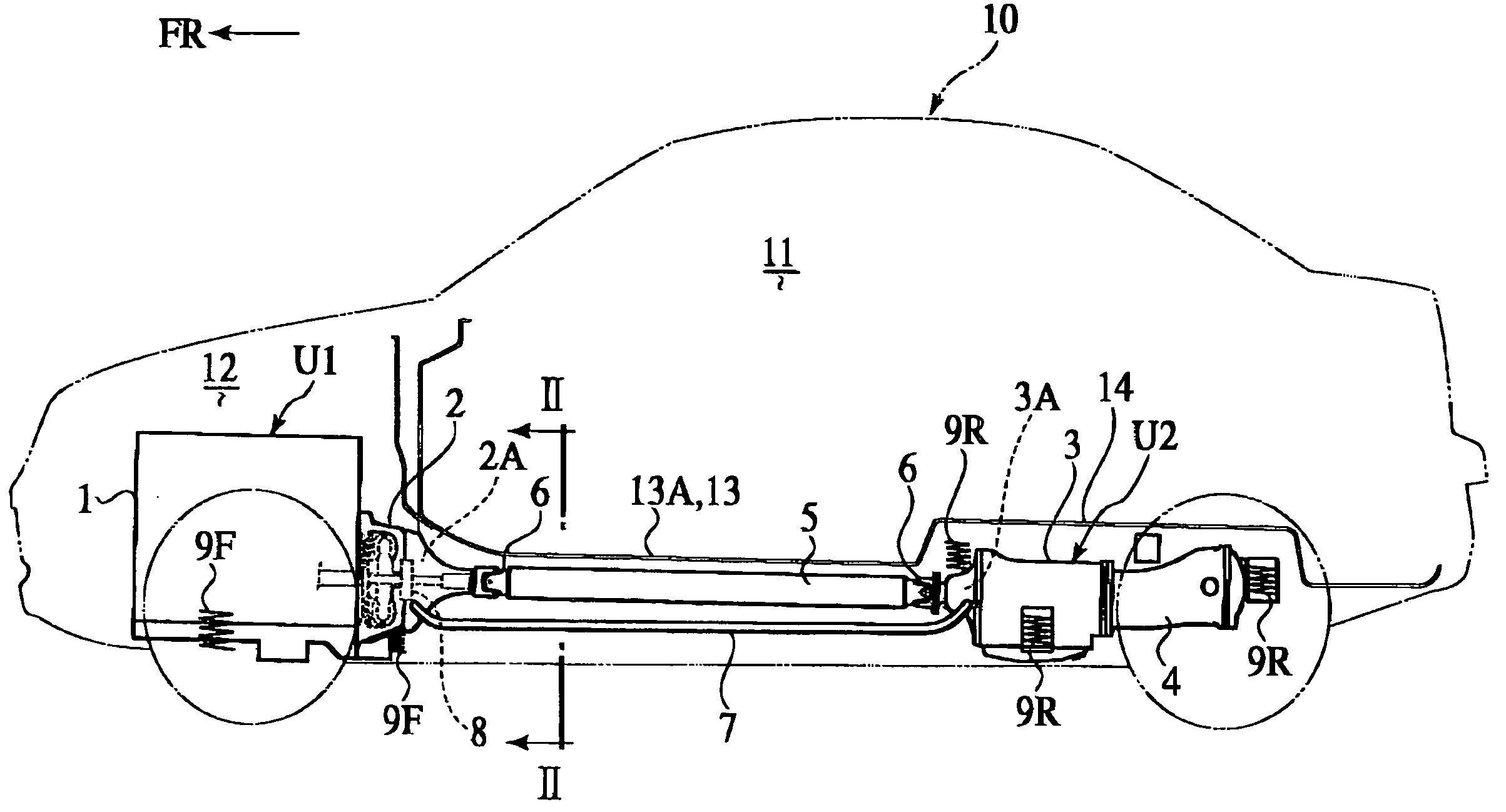
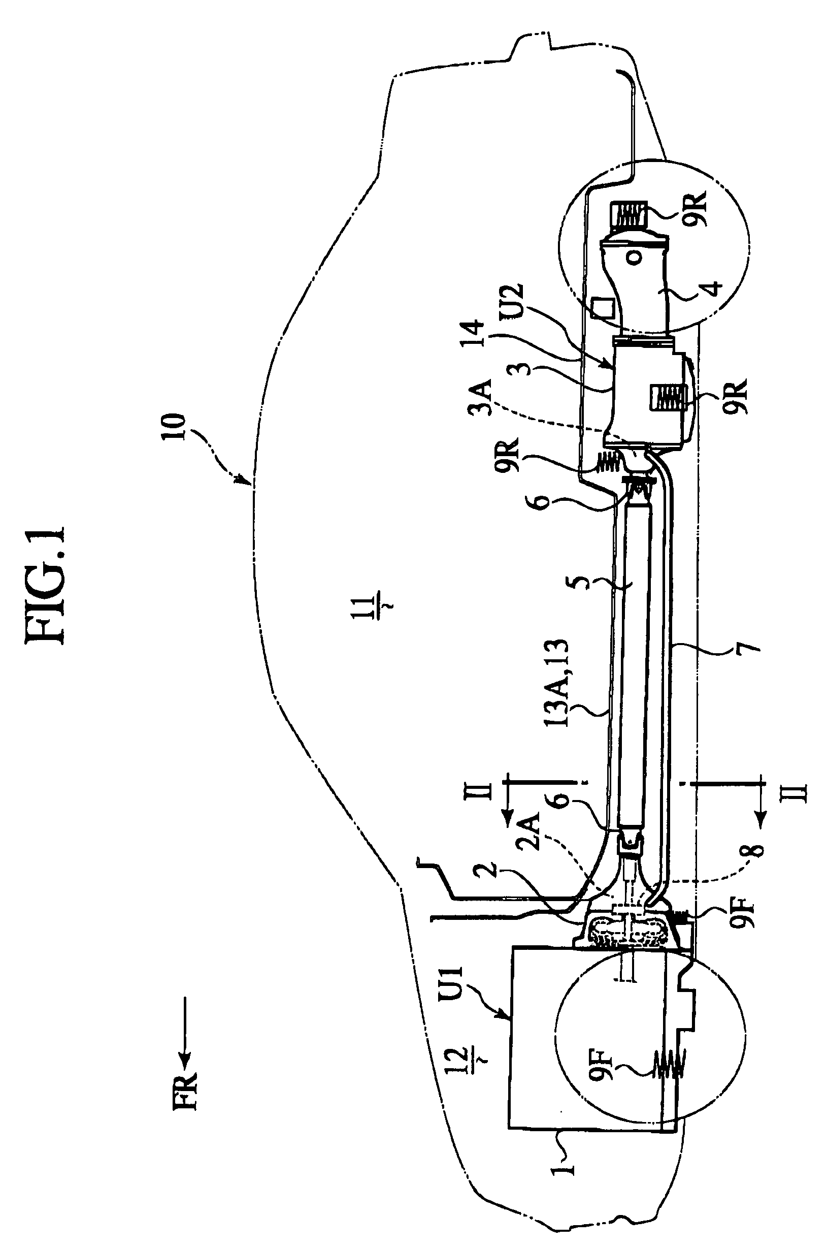
[0077] With a drive system of the embodiment, as shown in FIG. 1, a torque converter 2 and a transmission 3 are separated from one another. The torque converter 2 is assembled to a rear end of an engine 1 in a unitary structure to form a front drive unit U1. The transmission 3 is integrally assembled with a front end of a differential 4 to form a rear drive unit U2.
[0078] A vehicle of this embodiment is an A / T vehicle of a front engine with a rear drive type. The vehicle is shown as including a vehicle body 10 that has a vehicle compartment 11 and a front compartment 12, located in front of the vehicle compartment 11, in which the front drive unit U1 is installed. The rear drive unit U2 is mounted in an area beneath a rear floor 14. Thus, the front and rear drive units U1, U2 are separately located in front and rear areas of the vehicle body 10.
[0079] The front drive unit U1 is resiliently supported on sub frames or vehicle body front frame members at three ...
second embodiment
[0098] Second Embodiment
[0099] The second embodiment differs from the first embodiment in that the rear drive unit U2 is resiliently supported in a way to straddle a rear seat cross member 15 and a rear sub frame 16 as shown in FIG. 4.
[0100] Now, description is made focusing on such a different point.
[0101] The rear sub frame 16 supports the rear drive unit U2 at a rear end thereof. The rear sub frame 16 is formed with fore and aft frames 16A, 16B and a pair of side frames 16C in planar parallel crosses. The rear sub frame 16 has both fore and rear distal ends formed with rest portions 16D through which the rear sub frame 16 is coupled to a floor frame member joined to a lower surface of the rear floor 14. The differential 4 has a rear end that is resiliently supported on the rear frame 16B by means of a vibration-proof bush 17 that is located in and extends through a central area, along a vehicle widthwise direction, of the aft frame 16B in a fore and aft direction.
[0102] In the...
third embodiment
[0119] Third Embodiment
[0120]FIG. 10 shows a vehicle drive system of a third embodiment according to the present invention. Hereinafter, the same component parts as those of the second embodiment bear like reference numerals to omit redundant description.
[0121] With the structure of the third embodiment, the mount member 18 is a stay 13 having a vibration-proof mount member 22A by which the front portion of the transmission 3 is supported.
[0122] The stay 18B is made of lightweight metal, such as aluminum alloy, formed by die-casting. The stay 18B is formed in a structure that straddles the lower opening of the tunnel portion 15 of the rear seat cross member 15. Thus, the stay 18B has both lateral ends to be fixedly fastened to the left and right lower surfaces of the bottom walls of the rear seat cross member 15 on both sides of the lower opening.
[0123] Formed on a substantially central area of the stay 18B is a ridge portion 18′, on which a vibration-proof mount member 22A is lo...
PUM
 Abstract
Description
Claims
Application Information
 - R&D
- Intellectual Property
- Life Sciences
- Materials
- Tech Scout
- Unparalleled Data Quality
- Higher Quality Content
- 60% Fewer Hallucinations
Browse by: Latest US Patents, China's latest patents, Technical Efficacy Thesaurus, Application Domain, Technology Topic, Popular Technical Reports.
© 2025 PatSnap. All rights reserved.Legal|Privacy policy|Modern Slavery Act Transparency Statement|Sitemap|About US| Contact US: help@patsnap.com


