Pneumatic vehicle tire

Inactive Publication Date: 2005-03-24
MEYER GMBH +1
View PDF2 Cites 16 Cited by
  • Summary
  • Abstract
  • Description
  • Claims
  • Application Information

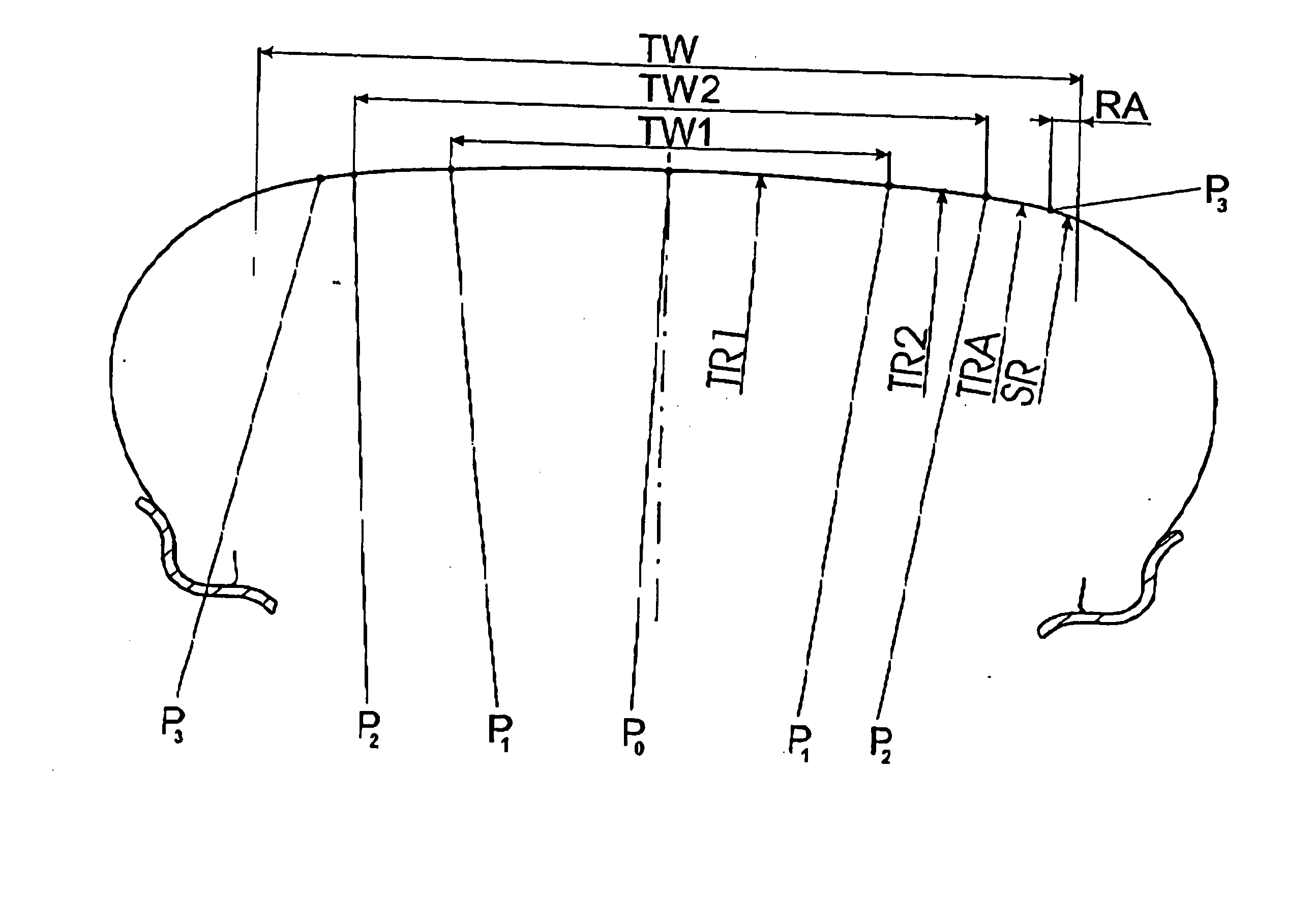
AI Technical Summary

Benefits of technology

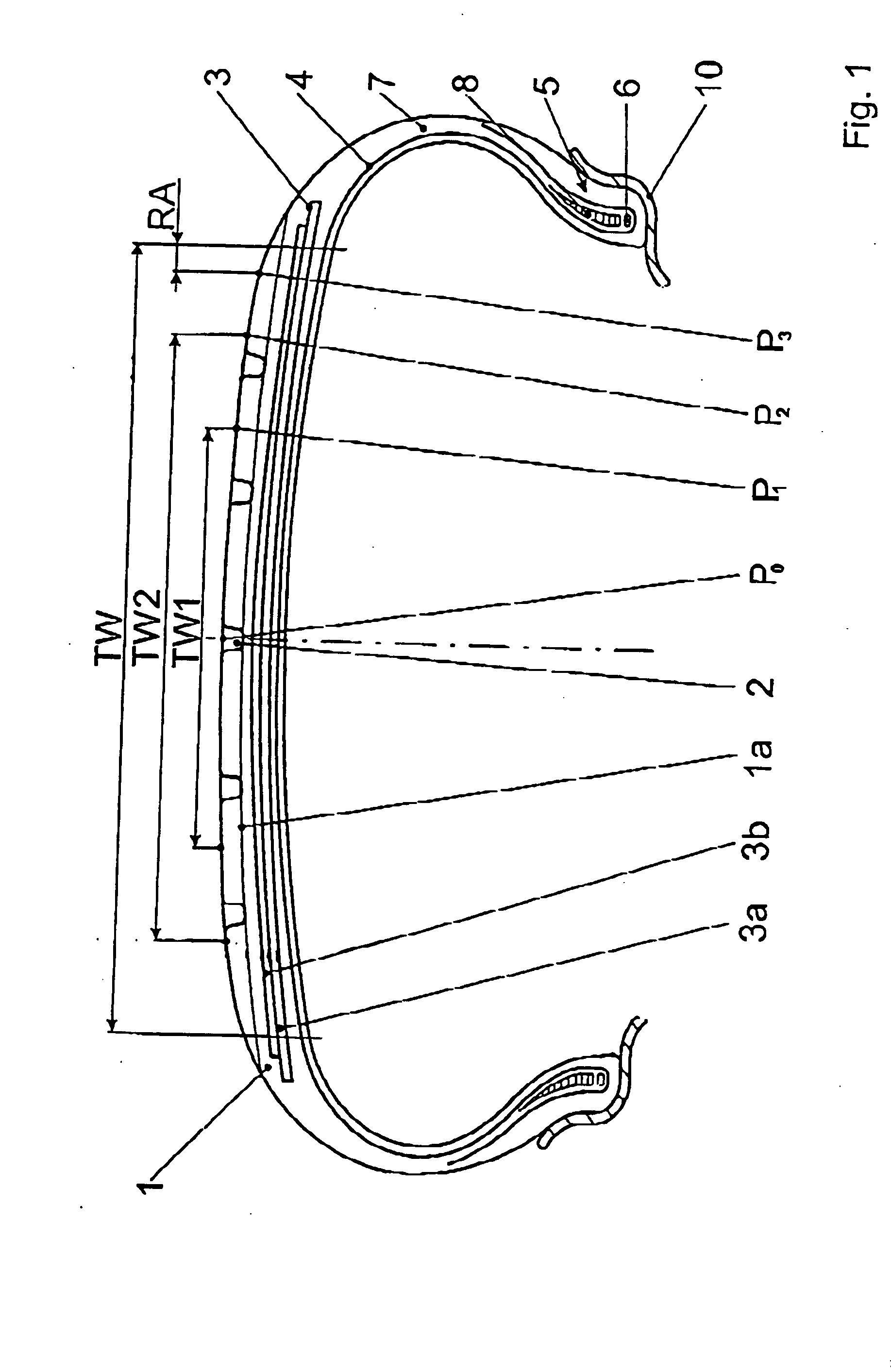
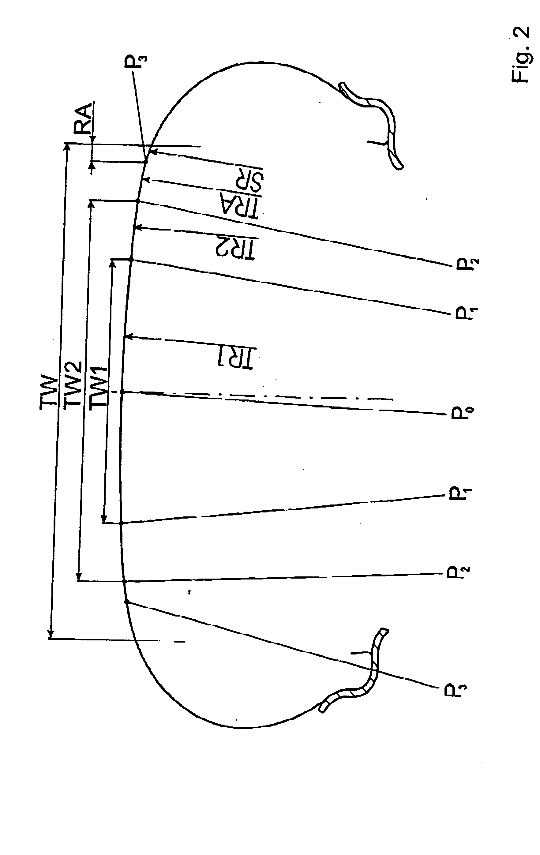
[0009] Consequently, according to the present invention the outer contour of the tread strip is so designed that it consists of an area with four different radii. This fundamentally permits a much better exercise of influence on the pressure distribution in the ground contact area. As has been shown, the interrelationship of the size of the individual radii is also significant for a equalization of the pressure distribution, especially the aforementioned relationship between the radius in the area encompassing the zenith of the tire and the radius of the radially outermost areas. Specifically, it is the last radius that makes it possible to exert influence on the volume in the shoulder areas outside the contact area. For example, with a relatively large radius in these areas a decrease of the volume in the shoulder areas outside the contact area is achieved. The rounder dynamic contour thus realized results in a lower temperature development in the tire and therefore an improved high-speed stability. The achievable uniformity of the pressure distribution has positive effects on various tire characteristics, such as braking behavior, handling and noise development.

Problems solved by technology

This elevated contact pressure in the shoulder areas negatively affects not only tire noise but also other tire characteristics, such as braking behavior, stability at higher speeds, rolling resistance and the hydroplaning characteristics.
With a 2-radii contour or a 3-radii contour, as known heretofore, it is indeed possible to achieve certain improvements in the pressure distribution in the ground contact area; however, even with complementary optimization of diverse parameters, it is not possible to influence the pressure distribution in the ground contact area of the tire to the desired extent or in desired manner.

Method used


Image

  • Pneumatic vehicle tire
  • Pneumatic vehicle tire
  • Pneumatic vehicle tire

Examples


Embodiment Construction

[0022] The depicted and described embodiment example pertains to a tire for an automobile. The invention is not, however, restricted to this type of tire and can just as easily be applied to other types of tires, e.g., truck tires.

[0023] The pneumatic vehicle tire shown in FIG. 1 is mounted on a merely indicated rim 10 and includes a tread strip 1, which is provided with a tread pattern, on which peripheral grooves (2) are depicted. The tread strip 1 runs laterally into the shoulder areas of the tire and is therefore wider than the tread width TW shown in FIG. 1. The tread width TW is the greatest width of the tire imprint (also called the contact area) on the ground when the tire is mounted on a suitable rim and placed under nominal pressure and nominal load. The illustrated peripheral grooves (2) extend to the preplanned maximum profile depth, which in general is chosen to be 7-8 mm. Other profile structures, e.g., grooves running in the transverse direction, can also be provided...


PUM


Abstract

A pneumatic vehicle tire of the radial type with a tread strip, which has a width defined as the tread width TW, which represents its maximal width in the ground contact area in the case of mounted, loaded and inflated tires, where, when viewed in cross section, the outer contour of the tread strip has at least three different radii over its width TW, of which the first radius TR1 extends over an area encompassing the zenith of the tire, while an adjoining area on both sides of this area has a radius TR2, which is smaller than the radius TR1, and while on each side of this area an adjoining area has a radius TRA, which is smaller than the radius TR1 of the area encompassing the zenith of the tire. In each case, the edges of the tread strip defined by the tread width TW run in an area with a fourth radius, a shoulder radius provided in the transition area to the sidewalls of the tire. The radius TRA is determined according to the equation 0.05 TR1≦TRA≦0.65 TR1. The radius TR2 can be either less than or greater than the radius TRA, where, for the case TR2≦TRA, the radius TR2 is determined according to the equation 0.05 TR1≦TR2≦0.6 TR1, and, for the case TR2≧TRA, the radius TR2 is determined according to the equation 0.1 TR1≦TR2≦0.95 TR1.

Description

INTRODUCTION AND BACKGROUND [0001] The present invention pertains to a pneumatic vehicle tire of the radial type with a tread strip, which has a width defined as the tread width TW, which represents its maximal width in the ground contact area in the case of mounted, loaded and inflated tires, where, when viewed in cross section, the outer contour of the tread strip has at least three different radii over its width TW, of which the first radius TR1 extends over an area encompassing the zenith of the tire, while an adjoining area on both sides of this area has a radius TR2, which is smaller than the radius TR1, and while on each side of this area an adjoining area has a radius TRA, which is smaller than the radius TR1 of the area encompassing the zenith of the tire. [0002] It is known that tires with their outer contour designed with only one radius, especially when these tires are provided with a low cross section, have a nonuniform pressure distribution in the ground contact area. ...

Claims


Application Information

Patent Timeline
IPC IPC(8): B60C11/00B60C11/01
CPCB60C11/00B60C11/01B60C11/0083
Inventor MEYER, ANDREASSOMMER, JURGEN
Owner MEYER GMBH
Why Eureka
Try Eureka