
Power supply circuit for traveling-wave tube which eliminates large relay and relay driving power supply

a power supply circuit and traveling wave tube technology, applied in the direction of transit tube circuit elements, circuit elements of cathode-ray/electron beam tubes, circuit elements of structural circuit elements, etc., can solve the problems of disadvantageous increase in size and cost of conventional power supply apparatus for traveling-wave tubes, and the general prone to destruction of relays, etc., to achieve low cost

Active Publication Date: 2005-03-17
NEC NETWORK & SENSOR SYST
View PDF4 Cites 13 Cited by
  • Summary
  • Abstract
  • Description
  • Claims
  • Application Information

AI Technical Summary

Benefits of technology

[0014] It is an object of the present invention to provide a small-size and low-cost circuit for powering a traveling-wave tube in a vibration and impact tolerable configuration.

Problems solved by technology

However, the foregoing conventional power supply apparatus implies the following problems.
Thus, the conventional power supply apparatus for a traveling-wave tube is disadvantageously increased in size and cost.
Also, since relays are generally prone to destruction due to vibrations and impacts, the power supply apparatus for a traveling-wave tube is disadvantageously vulnerable to vibrations and impacts.

Method used


Image

  • Power supply circuit for traveling-wave tube which eliminates large relay and relay driving power supply
  • Power supply circuit for traveling-wave tube which eliminates large relay and relay driving power supply
  • Power supply circuit for traveling-wave tube which eliminates large relay and relay driving power supply

Examples


Embodiment Construction

[0024] One embodiment of the present invention will be described in detail with reference to the accompanying drawings.

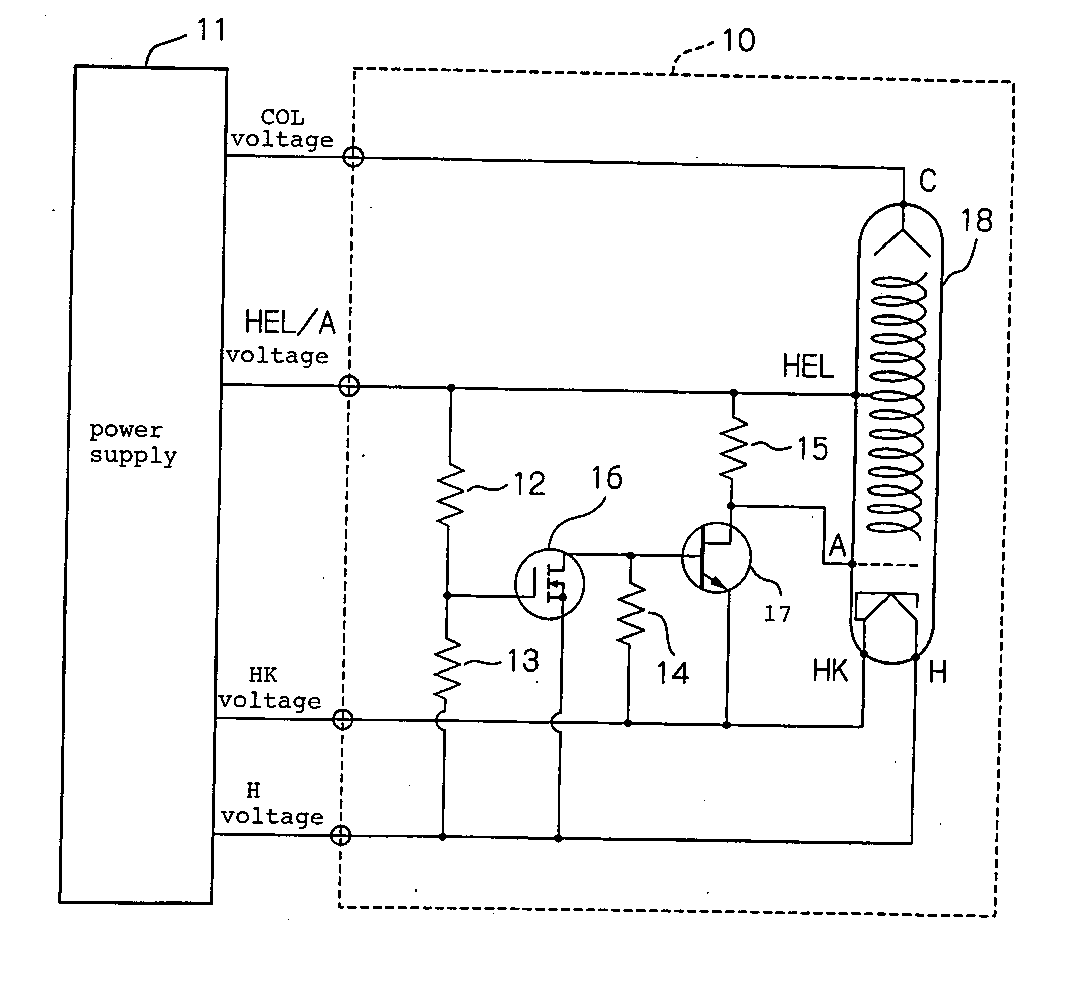
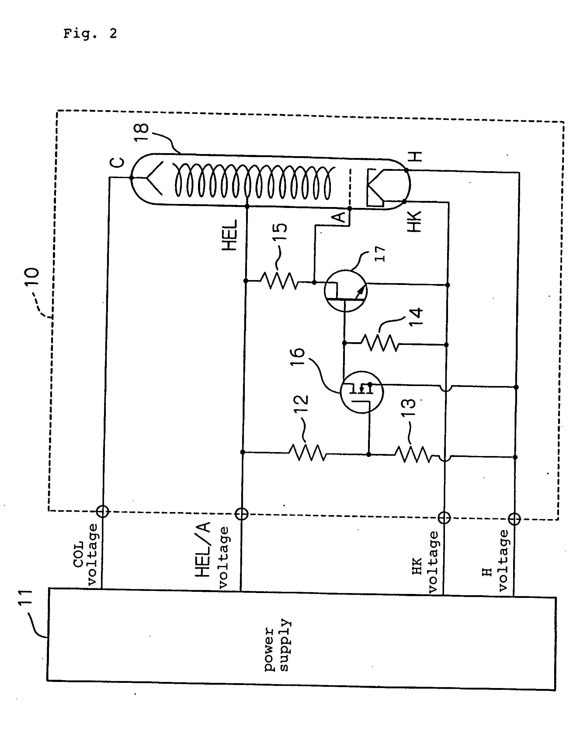
[0025]FIG. 2 is a block diagram illustrating a traveling-wave tube apparatus according to one embodiment of the present invention. Referring to FIG. 2, traveling-wave tube apparatus 10 of this embodiment comprises resistors 12-15, FETs 16, 17, and traveling-wave tube 18.

[0026] One electrode is commonly used as a heater electrode and a cathode electrode on the positive side of traveling-wave tube 18, so that this electrode is called the “heater / cathode electrode.” Also, a heater electrode on the negative side of traveling-wave tube 18 is simply called the “heater electrode.”

[0027] Traveling-wave tube apparatus 10 of this embodiment is supplied with a variety of voltages from power supply 11. Power supply 11, which is a high-voltage power supply for a traveling wave tube, supplies a collector voltage (COL voltage) to a collector electrode (C in the figure) of travel...


PUM


Abstract

A power supply circuit for a traveling-wave tube disclosed herein eliminates a large relay and a relay driving power supply to reduce the size and cost and to make itself tolerable to vibrations and impacts. A first control device turns on, when a potential on a helix electrode rises to a predetermined threshold determined by the ratio of the resistance of a first resistor to the resistance of a second resistor with respect to a potential on a positive heater electrode or a negative heater electrode, to conduct from a first terminal to a second terminal of the first control device. A second control device turns on when the first control device is off to maintain an anode electrode and a cathode electrode at the same potential. The second control device turns off when the first control device turns on to generate a potential difference between the anode electrode and cathode electrode, thereby applying a voltage to the anode electrode.

Description

BACKGROUND OF THE INVENTION [0001] 1. Field of the Invention [0002] The present invention relates to a power supply circuit for powering a traveling-wave tube. [0003] 2. Description of the Related Art [0004] A traveling-wave tube must be supplied with a variety of voltages such as a heater voltage, a cathode voltage, a helix voltage, and a collector voltage. In addition, the respective voltages are sequentially applied in accordance with a predetermined procedure called an “anode sequence” in order to prevent excessive currents. After a heater has been sufficiently heated by the heater voltage applied thereto (for example, in several minutes), the helix voltage is applied. Then, according to the anode sequence, the anode voltage is applied later than the helix voltage. [0005] For powering a traveling-wave tube in accordance with an anode sequence as mentioned above, a circuit including a relay has been conventionally required, and power supply apparatuses for traveling-wave tubes ha...

Claims


Application Information

Patent Timeline
IPC IPC(8): H01J7/44H01J25/34H01J23/34
CPCH01J25/34H01J23/34
Inventor ABIKO, SHUJIFUJIWARA, EIJI
Owner NEC NETWORK & SENSOR SYST
Learn More