Optical displacement sensor and external force detecting device
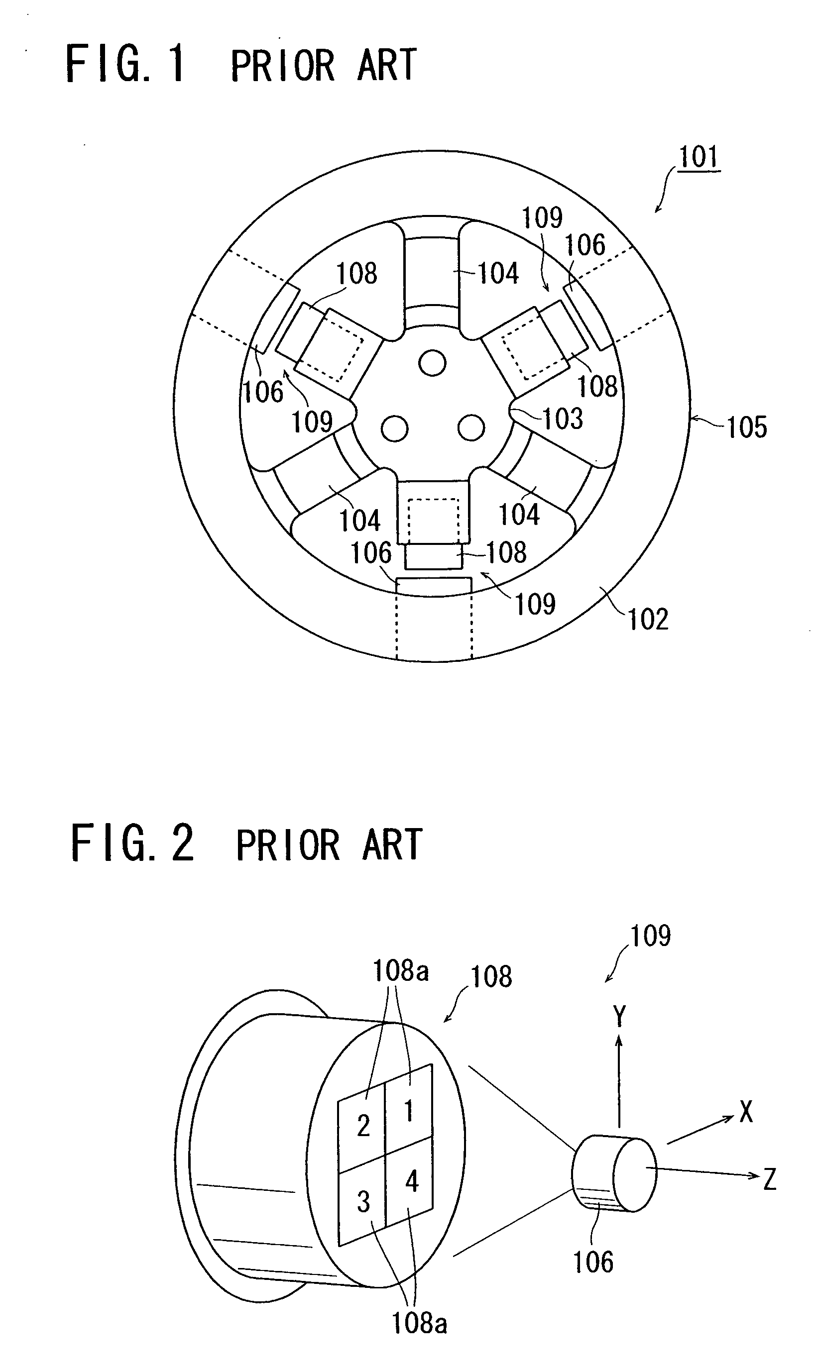
a technology of optical displacement sensor and detecting device, which is applied in the direction of instruments, instruments, and instruments for force/torque/work measurement, etc., can solve the problems of affecting the accuracy of the measurement, the adjustment of the rotational angle about the z-axis perpendicular to the x- and y-axes is difficult, and the work is laborious, so as to reduce the time, the adjustment is easy, and the effect of reducing the tim
- Summary
- Abstract
- Description
- Claims
- Application Information
AI Technical Summary
Benefits of technology
Problems solved by technology
Method used
Image
Examples
first embodiment
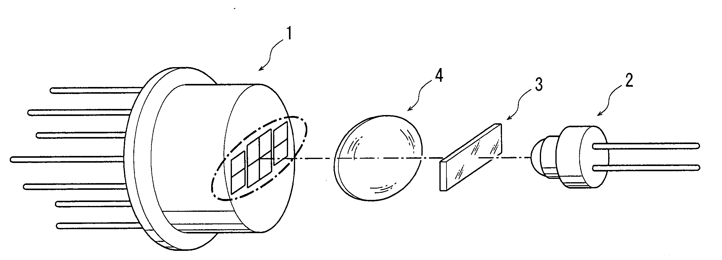
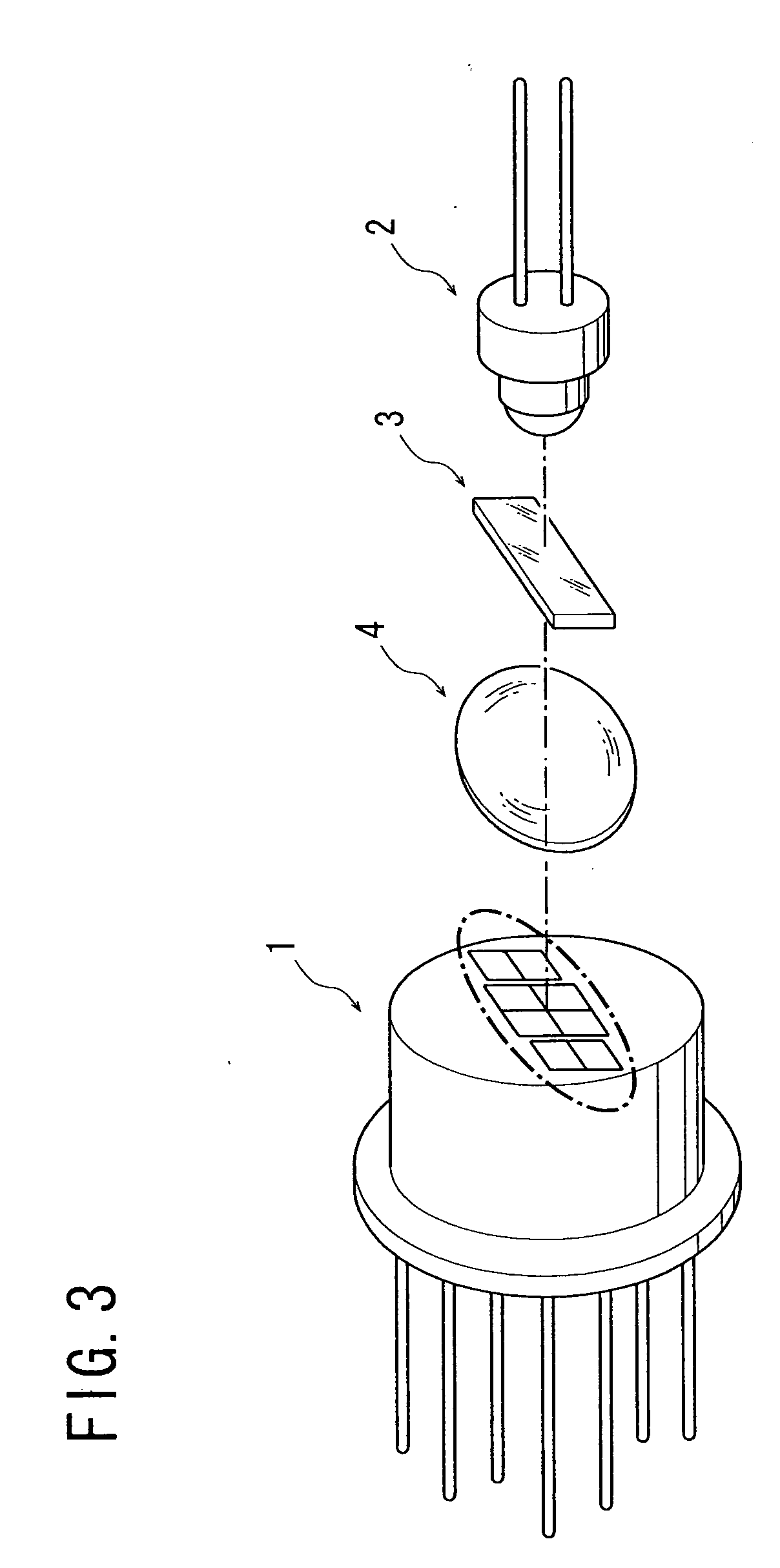
[0034] the present invention will be described with reference to FIGS. 3 to 6. Referring first to FIG. 3, an optical displacement sensor comprises: a photodiode (PD) assembly 1 as a light receiving means; a light emitting diode (LED) 2 which is a light emitting element as a light source; a light diffracting element 3 to disperse one beam into three beams; and a lens 4 to shape and condense beams.
[0035] In the optical displacement sensor shown in FIG. 3, the PD assembly 1 is mounted at one of a reference object and a measurement object, and the LED 2 is mounted at the other one thereof, at which the PD assembly 1 is not mounted, wherein light emitted from the LED 2 is received at the PD assembly 1, and the positional displacement of the measurement object relative to the reference object with respect to two-axis directions in a plane perpendicular to the optical axis of the light emitted from the LED 2 is measured on the basis of the state of light reception at the PD assembly 1. Thi...
second embodiment
[0044] the present invention will be described with reference to FIGS. 2, 8, and 9A to 9F. Referring to FIG. 7, an optical displacement sensor according to the second embodiment comprises a PD assembly 15 as a light receiving means, and a laser source 16 as a light source. Light emitted from the laser source 16 has its light intensity distribution shaped oval in cross section with two axes of symmetry crossing at right angles, and this distribution shape is leveraged into the optical displacement sensor according to the second embodiment.
[0045] Referring to FIG. 8, the PD assembly 15 is of a conventional structure, specifically has four PD's 15a to 15d arranged at its light receiving face, and light 16a emitted from the laser source 16 impinges on the light receiving face of the PD assembly 15. The optical axis of the light 16a is oriented perpendicular to the light receiving face, and it is preferred that the center of the light 16a be positioned at the center of an area occupied b...
PUM
| Property | Measurement | Unit |
|---|---|---|
| displacement | aaaaa | aaaaa |
| external force | aaaaa | aaaaa |
| equi-angular distance | aaaaa | aaaaa |
Abstract
Description
Claims
Application Information
 - R&D
- Intellectual Property
- Life Sciences
- Materials
- Tech Scout
- Unparalleled Data Quality
- Higher Quality Content
- 60% Fewer Hallucinations
Browse by: Latest US Patents, China's latest patents, Technical Efficacy Thesaurus, Application Domain, Technology Topic, Popular Technical Reports.
© 2025 PatSnap. All rights reserved.Legal|Privacy policy|Modern Slavery Act Transparency Statement|Sitemap|About US| Contact US: help@patsnap.com


