
Medical device

Inactive Publication Date: 2005-03-03
RANIER LIMITED
View PDF24 Cites 22 Cited by
  • Summary
  • Abstract
  • Description
  • Claims
  • Application Information

AI Technical Summary

Benefits of technology

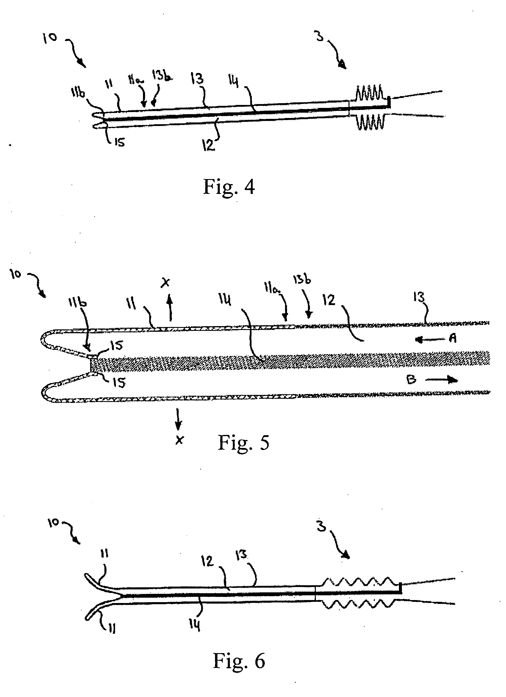
[0009] One advantage of the embodiment is that it may be possible to retract both the tip and the retention section into the drainage section and thus during insertion of the medical device the uneven surface of the retention section is not in contact with the body e.g. a mucous membrane. This will increase the comfort of the living being as it then renders possible to make a medical device wherein only even and smooth surfaces e.g. of the drainage section, are in contact with the mucous membrane during insertion, especially If said surfaces are lubricated or hydrophilic. At the same time the anchoring advantages of the retention section may be utilised as the retention section may be pushed out of the drainage section once the medical device is inserted into the living being e.g. into a urine bladder.
[0016] In a third embodiment the medical device is designed such that the predetermined shape when the retention section is located inside the remaining part of the medical device, e.g. the drainage section, coaxially therewith. When the medical device is located in the body, the second part is displaced out of the remaining part of the medical device to form a medical device in the second configuration, i.e. retained in the body. To operate the medical device between the different configurations, a deployment member could be fastened in the proximal end, e.g. to a proximal tip of the medical device, and extend to the distal end to facilitate manipulation of the proximal end from outside the body. To facilitate comfortable insertion or to reduce adherence of body tissue to the surface of the medical device, at least a part of the medical device, e.g. the braided portion or the second part of the braided portion or the tip-part may have an outer surface, i.e. a surface towards the body tissue when the medical device is inserted into the body, which surface has a low surface friction characteristic compared to other parts of the medical device. To provide the low friction characteristic, the braided portion or at least the second part thereof may have a hydrophilic surface, e.g. provided by a hydrophilic coating of the surface. If a hydrophilic coating is applied to the braided portion, the coating may incorporate an anti-infective compound or a compound which counteracts ingrowth. A hydrophilic coating may further reduce irritation of the body tissue, e.g. mucosa.
[0025] By providing a drainage section comprising a braided material, the strength of the drainage section is reinforced as the braided section and an appropriate filling material constitutes a composite. Accordingly it is possible to make the wall of the drainage section thinner. Thus for a given outer diameter of the medical device the cross-sectional flow area may be larger.
[0032] In one embodiment the medical device further comprises indicating means for indicating a position of the tip relative to the retention section or relative to the drainage section. Such indicating means are useful as it is not possible for the user to see if the tip after having been retracted into the drainage section during insertion, has been pushed out of the drainage section again. Thus the indicating means may assist the user to see that the tip does not partly or completely block the drainage section.
[0033] Furthermore by providing means e.g. at the distal end which indicates the position of the tip of the medical device in relation to the retention section it is possible for the user to retract the tip to a position wherein the it is shielded by the retention section and at the same time does not block the conduit of the drainage section. Accordingly the tip may not irritate the inner wall of the bladder and increased flow is ensured.
[0034] According to a second aspect the present invention relates to the use of a medical device as described in this application for increasing the comfort of a patient during insertion of the device. As described above the medical device may ease the comfort for the patient

Problems solved by technology

Many people suffer from a variety of medical problems that require the insertion of a medical device such as a catheter, to drain fluids from the body.

Method used


Image

  • Medical device
  • Medical device
  • Medical device

Examples


first embodiment

[0014] The medical device, especially the retention section, may be designed with “shape-memory” such that it will automatically move towards a predetermined shape i.e. towards a relaxed state. In a first embodiment the medical device is designed such that the predetermined shape is the first configuration, i.e. the medical device will have a tendency to move towards the first configuration, but may be moved into the second configuration by axial displacement of the first part of the braided portion into a second part of the braided portion. In some embodiments the first configuration is a configuration wherein the largest dimension of a cross-section of the retention section is equal or less than the largest dimension of a cross-section of the drainage section.

second embodiment

[0015] In a second embodiment the medical device is designed such that the predetermined shape is the second configuration, i.e. the medical device will have a tendency to move towards the second configuration, but may be moved into the first configuration by axial displacement of the first part of the braided portion out of the second part of the braided portion. In some embodiments the second configuration is a configuration wherein the largest dimension of a cross-section of the retention section is larger than the largest dimension of a cross-section of the drainage section.

third embodiment

[0016] In a third embodiment the medical device is designed such that the predetermined shape when the retention section is located inside the remaining part of the medical device, e.g. the drainage section, coaxially therewith. When the medical device is located in the body, the second part is displaced out of the remaining part of the medical device to form a medical device in the second configuration, i.e. retained in the body. To operate the medical device between the different configurations, a deployment member could be fastened in the proximal end, e.g. to a proximal tip of the medical device, and extend to the distal end to facilitate manipulation of the proximal end from outside the body. To facilitate comfortable insertion or to reduce adherence of body tissue to the surface of the medical device, at least a part of the medical device, e.g. the braided portion or the second part of the braided portion or the tip-part may have an outer surface, i.e. a surface towards the bo...


PUM


Abstract

1. A medical device with a proximal end for insertion into a body of a living being and an axially opposite distal end, the device comprising: a tip which in a first position forms the proximal end of the device, a drainage section forming a conduit extending in an axial direction of the device, and a retention section extending between the draining section and the tip, wherein the tip is operable between the first position and a second position so as to move the retention section between a first configuration and a second configuration, in which second configuration the retention section is expanded in a direction transverse to the axial direction. The conduit and the tip may be dimensioned to allow the tip to be received within the conduit. One advantage of such a system is that the retention system may be retracted entirely into the conduit so as to make insertion and retraction of the device more comfortable for the patient.

Description

[0001] The present invention relates to a medical device for draining fluids from the body of a living being. In particular, the invention relates to a medical device with a proximal end for insertion into a body of a living being and an axially opposite distal end, the device comprising: a tip which in a first position forms the proximal end of the device, a drainage section forming a conduit extending in an axial direction of the device, and a retention section extending between the draining section and the tip, wherein the tip is operable between the first position and a second position so as to move the retention section between a first configuration and a second configuration, in which second configuration the retention section is expanded in a direction transverse to the axial direction. More specifically the present invention relates to a medical device wherein the conduit and the tip are dimensioned to allow the tip to be received within the conduit. BACKGROUND OF THE INVENT...

Claims


Application Information

Patent Timeline
IPC IPC(8): A61M25/00A61M29/00
CPCA61M27/008
Inventor SNELL, ROBERTMARTIN, SAMCABLE, MARTINKING, ELEANORE
Owner RANIER LIMITED
Learn More