
Hypocycloid reducing apparatus

Inactive Publication Date: 2005-03-03
SPEEDSTAR IND
View PDF3 Cites 4 Cited by
  • Summary
  • Abstract
  • Description
  • Claims
  • Application Information

AI Technical Summary

Benefits of technology

[0007] The main objective of the invention is to provide a hypocycloid reducing apparatus operating as a speed reduction and torque multiplier mechanism, wherein the hypocycloid reducing apparatus is quiet, compact and durable.

Problems solved by technology

Although, the reducing gears can change the speed of rotation to a required speed of rotation for the rotating shaft, noises will be generated during a period of the gear operating.
Besides, as an arrangement of the gears in the gear reducer always occupies a huge space, the gear reducer will be bulky.
However, a hypocycloid reducing apparatus is not widely used in engineering designs because few mechanical engineers understand the design principle of the hypocycloid reducing apparatus.

Method used


Image

  • Hypocycloid reducing apparatus
  • Hypocycloid reducing apparatus
  • Hypocycloid reducing apparatus

Examples


Embodiment Construction

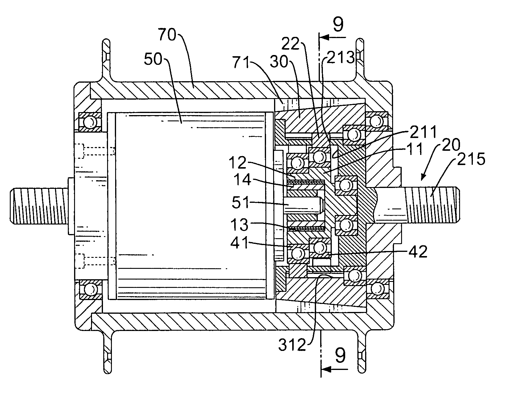
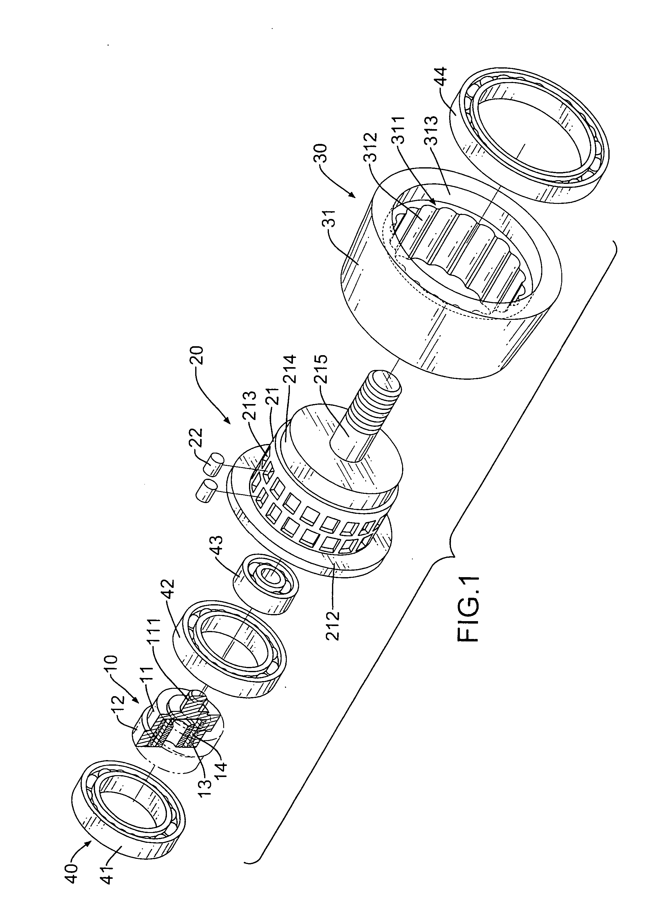
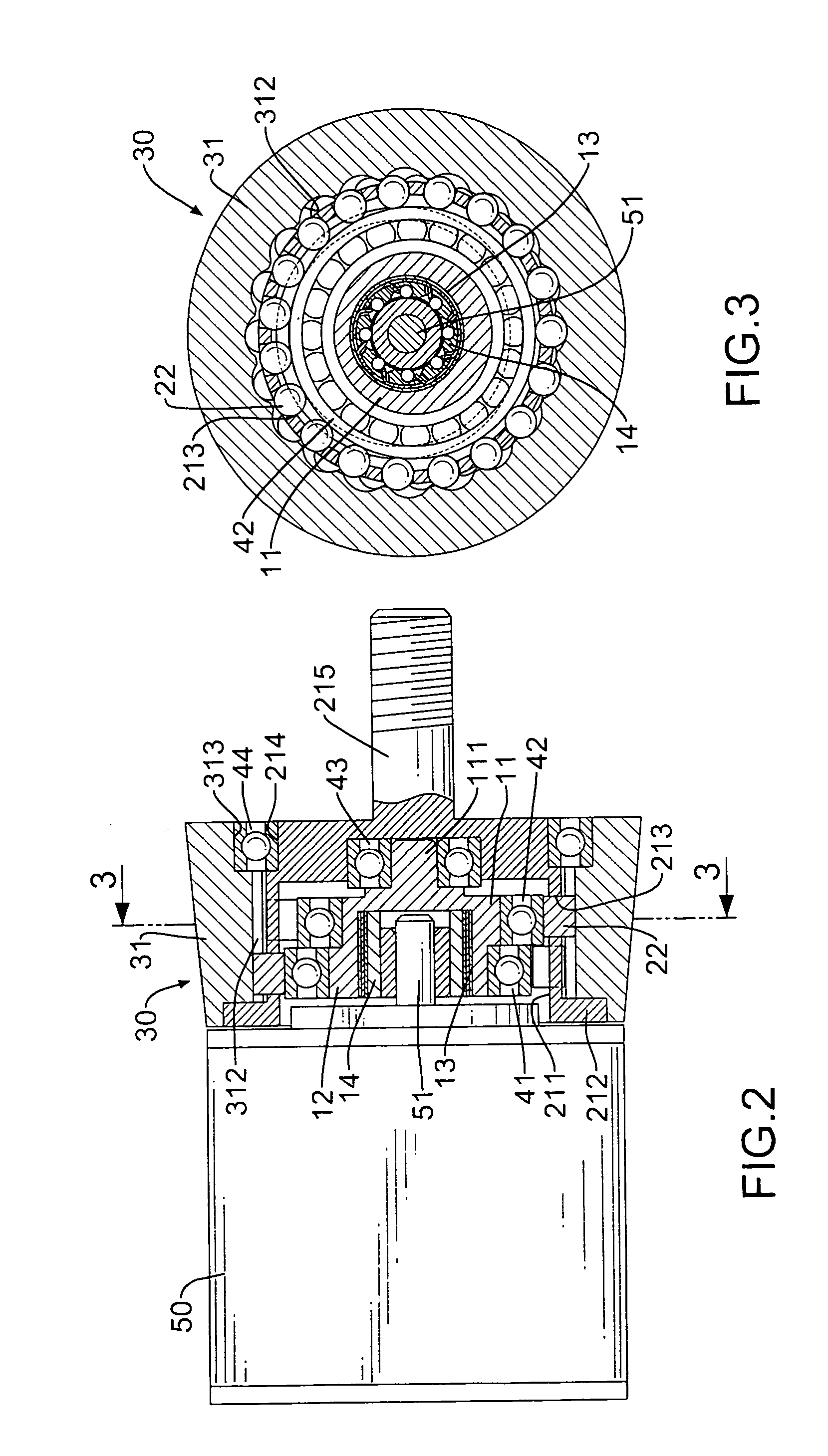
[0018] With reference to FIGS. 1 to 3, a hypocycloid reducing apparatus in accordance with the present invention is connected to a rotating mechanism, such as a motor (50) having a driving shaft (51), to reduce a speed of revolutions of the motor driving shaft (51). The hypocycloid reducing apparatus comprises a driven input (10), an inside bracket (20), an outside bracket (30) and multiple bearings (40) including a one-directional bearing (14). One of the inside bracket (20) and the outside bracket (30) is stationary, and the other is rotatable. For convenient illustrating purpose only, the inside bracket (20) is rotatable and the outside bracket (30) is stationary in the following description.

[0019] The driven input (10) is coupled to the driving shaft (51) of the motor (50) and is rotated by the driving shaft (51). The driven input (10) has a proximal end (not numbered), a distal end (not numbered), an off-center assembly (not numbered), a blind hole (13) and a pivot shaft (111)...


PUM


Abstract

A hypocycloid reducing apparatus includes a hollow outside bracket, a hollow inside bracket and a driven input that is rotated by a rotating mechanism, such as a motor. The outside bracket has a passage with N quantity of lobe grooves. The inside is rotatably mounted in the passage of the outside bracket and has an inner space, M quantity of through holes and an output shaft. The through holes are arranged in an annular arrangement, are aligned with the lobe grooves and each through hole holds a roller. The driven input is mounted rotatably in the inner space and has an off-center assembly to encounter sequentially with each roller to actuate rotating the inside bracket. Therefore, a speed of revolution of the rotating mechanism is reduced to the output shaft. A volume of the reducing apparatus is minimized, as is noise produced during operation.

Description

BACKGROUND OF THE INVENTION [0001] 1. Field of the Invention [0002] The present invention relates to a revolution reducing apparatus, and more particularly to hypocycloid reducing apparatus that is quiet and compact. [0003] 2. Description of Related Art [0004] Reducing gears, also called reducers are typically coupled to motors for reducing revolution speeds of the motors. The reducers are widely used in many engineering designs. However, the reducers today are generally applied to gears, such as planetary gears to achieve a purpose of reducing revolutions of a rotating shaft. Although, the reducing gears can change the speed of rotation to a required speed of rotation for the rotating shaft, noises will be generated during a period of the gear operating. Besides, as an arrangement of the gears in the gear reducer always occupies a huge space, the gear reducer will be bulky. [0005] A hypocycloid reducing apparatus works as a speed reduction and torque multiplier mechanism that is qu...

Claims


Application Information

Patent Timeline
IPC IPC(8): F16H1/32
CPCF16H1/32
Inventor HSIEH, WEN-CHAN
Owner SPEEDSTAR IND
Learn More