Eureka AIR delivers breakthrough ideas for toughest innovation challenges, trusted by R&D personnel around the world.

Tubular member made of fluororesin

a tubular member and fluororesin technology, applied in the field of fluororesin tubular members, can solve the problems of reducing gas permeability, unable to use countermeasures such as establishing a multi-layered, and affecting the gas flow rate, so as to reduce gas leakage and condensation on the tube surfa

Inactive Publication Date: 2005-03-03
JUNKOSHA
View PDF13 Cites 4 Cited by
  • Summary
  • Abstract
  • Description
  • Claims
  • Application Information

AI Technical Summary

Benefits of technology

[0008] It is an object of the present invention to use a hose, tube, or other fluororesin tubular member to prevent gases from leaking, and the leaked vapor from condensing on the tube surface, by means of reducing the gas permeability without compromising the chemical resistance and other exceptional characteristics inherent in the fluororesin.
[0014] The fluororesin tubular member of the present invention is stretched and heat set after molding, making it possible to obtain a product in which the gas permeability is reduced and the chemical resistance or other characteristics remain unaffected in comparison with those of the pre-stretched fluororesin tubular member. It is accordingly possible to provide a fluororesin tube in which gas leakage and condensation on the tube surface is reduced when the tube is used for supplying chemicals in semiconductor manufacturing processes or the like.

Problems solved by technology

On the other hand, problems are encountered when hoses, tubes, or the like made from fluororesins are used to convey pure water or other fluids in applications ranging from semiconductor manufacturing processes to those wherein chemical resistance is demanded; i.e., when gases dissolved in fluids, or vapors from these fluids leak from such tubes or the like, and these leaked gases may condense on the surfaces of the tubes or the like, causing the area surrounding the tube to get wet from the liquid.
However, tubes made of fluororesins are employed in applications requiring chemical resistance, or requiring the pollution caused as a result of substances eluting from the tube to be prevented, which renders impossible the use of countermeasures such as establishing a multilayered structure or adding other substances to the fluororesin composition in order to lower the gas permeability.

Method used


Image

  • Tubular member made of fluororesin

Examples


##ventive example 1

INVENTIVE EXAMPLE 1

[0029] A tube having an inside diameter of 13.4 mm and an outside diameter of 17.9 mm was fabricated as a result of passing tetrafluoroethylene-fluoroalkyl vinyl ether copolymer (PFA451HP-J; manufactured by Du Pont-Mitsui Fluorochemicals Co., Ltd.) from a single-screw extruder having a die temperature of 380° C. through a former.

[0030] The tube was subsequently stretched 600% at a temperature of 280° C., a travelling speed of 0.17 m / min, and a pulling speed of 1.0 m / min, whereupon an annealing treatment was performed at a temperature of 220° C., a travelling speed of 0.60 m / min, and a pulling speed of 0.50 mm / min, and a 20% shrinkage treatment was performed.

TEST METHOD

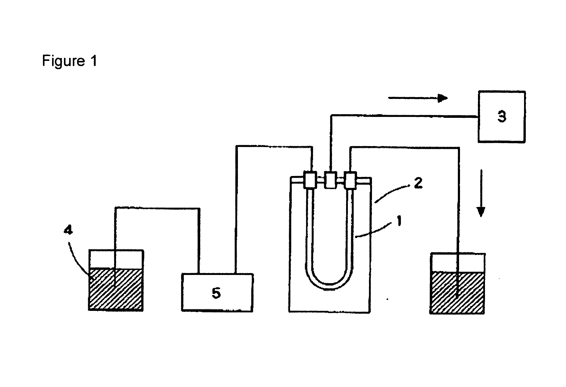
[0031] As shown in FIG. 1, the flow rate of a metering pump 5 was varied to feed oxygen-saturated purified water 4 at a temperature of 25° C. to a 1080 mm sample tube 1, which was attached to a decompression vessel 2. The oxygen concentration was 8.1 ppm. In this configuration, the decompression v...

##ventive example 2

INVENTIVE EXAMPLE 2

[0034] A tube having an inside diameter of 12.2 mm and an outside diameter of 16.3 mm was fabricated as a result of passing tetrafluoroethylene-hexafluoropropylene copolymer (FEP NP-20; manufactured by Daikin Industries Ltd.) from a single-screw extruder having a die temperature of 380° C. through a former.

[0035] The tube was subsequently stretched 500% at a temperature of 230° C., a travelling speed of 0.20 m / min, and a pulling speed of 1.0 m / min, whereupon an annealing treatment was performed at a temperature of 180° C., a travelling speed of 0.60 m / min, and a pulling speed of 0.50 mm / min, and a 20% shrinkage treatment was performed.

[0036] The gas permeability of Inventive Example 2 (length: 1090 mm) was measured in the same manner as in Inventive Example 1. The results for Inventive Example 2 are displayed in Table 2.

##ventive example 3

INVENTIVE EXAMPLE 3

[0039] A tube having an inside diameter of 13.4 mm and an outside diameter of 17.9 mm was fabricated as a result of passing tetrafluoroethylene-fluoroalkyl vinyl ether copolymer (950HP-plus; manufactured by Du Pont-Mitsui Fluorochemicals Co., Ltd.) from a single-screw extruder having a die temperature of 380° C. through a former.

[0040] The tube was subsequently stretched 600% at a temperature of 280° C., a travelling speed of 0.15 m / min, and a pulling speed of 0.9 m / min, whereupon an annealing treatment was performed at a temperature of 200° C., a travelling speed of 0.60 m / min, and a pulling speed of 0.50 mm / min, and a 20% shrinkage treatment was performed.

[0041] The gas permeability of Inventive Example 3 (length: 1100 mm) was measured in the same manner as in Inventive Example 1. The results for Inventive Example 3 are displayed in Table 3.


PUM

PropertyMeasurementUnit
diameteraaaaaaaaaa
diameteraaaaaaaaaa
die temperatureaaaaaaaaaa

Abstract

The invention relates to a fluororesin tube. More specifically, the invention provides a fluororesin tubular member that has low gas permeability. The fluororesin tubular member of the present invention uses a fluororesin as a starting material and is stretched in the axial direction and heat set once molding has been performed. Gas permeability may accordingly be reduced as compared to tubular bodies obtained merely by means of the molding of a fluororesin; therefore, if the tubular member is used as a material for chemical supply lines or other pipework that requires a fluororesin tube, it is possible to prevent gas from leaking and condensation from forming on the piping surface.

Description

FIELD OF THE INVENTION [0001] The present invention relates to a fluororesin tubular member, and, when used as a hose, tube, or other means to convey fluids or the like, relates to a fluororesin tubular member having exceptional gas-barrier properties with minimal gas permeability. BACKGROUND OF THE INVENTION [0002] Materials made of fluororesins are extensively used in applications ranging from semiconductor manufacturing processes to those wherein chemical resistance is required. For example, hoses, tubes, and other tubular members manufactured from fluororesin materials by means of extrusion molding are employed in pipework used for fluids. [0003] However, tubular members made of fluororesins have the characteristic of being highly gas-permeable, so that films and tubes made from tetrafluoroethylene-fluoroalkyl vinyl ether copolymer (PFA), tetrafluoroethylene-hexafluoropropylene copolymer (FEP), and polytetrafluoroethylene (PTFE), which are extensively used fluororesins, may be e...

Claims


Application Information

Patent Timeline
Patent Type & Authority Applications(United States)
IPC IPC(8): F16L11/04B29C48/00B29C48/09B29C55/22B29C71/00B29C71/02B29K27/12B29L23/00F16L9/12
CPCB29C47/00B29C47/0023B29C55/22B29C71/0063B29C71/02Y10T428/1397B29K2027/12B29K2105/258B29K2995/0067F16L9/12B29C2071/022B29C48/00B29C48/09B29C55/00B29C71/00
Inventor HAYASHI, YUKIHIKOSUZUKI, MASAHIRO
Owner JUNKOSHA
Why Eureka
Eureka Blog
Learn More