
Dry safety device for an inflammable gas

a safety device and inflammable gas technology, applied in dental surgery, lighting and heating apparatus, combustion types, etc., can solve the problems of dangerous condition, dry safety device not functioning, safety device not constructed to prevent the counter flow of gas

Active Publication Date: 2005-03-03
SANKI CO LTD
View PDF7 Cites 7 Cited by
  • Summary
  • Abstract
  • Description
  • Claims
  • Application Information

AI Technical Summary

Benefits of technology

The present invention provides a dry safety device for an inflammable gas that can shut off the gas passage not only when counter flow of the inflammable gas occurs but also when the ambient temperature rises too high. The device has a high-temperature shutoff mechanism with a shutoff valve located at a position where the shutoff valve is not exposed to flames during back fire so that the high-temperature shutoff mechanism can be securely operated when serious situations such as fire occur. The device is rugged in construction and reliable in operation under a wide range of conditions.

Problems solved by technology

However, this safety device is not constructed to prevent the counter flow of gas in situations when a counter-flow pressure is not produced.
In such a state, if a serious situation occurs in the surrounding environment and the ambient temperature is raised too high, or if a fire happens, the hose may be broken and fire may enter the hose, creating a very dangerous condition.
Namely, in a conventional dry safety device which is operated by the counter-flow pressure produced by back fire, in the event the hose is broken and the gas escaping from the broken hose simply burns, a counter-flow pressure is not generated and in such a state, this dry safety device does not function.
However, since this shutoff valve is disposed at the secondary side open port, when a counter flow accompanied by back fire occurs, flames that reach the shutoff valve pass the periphery of the elastic packing and damage the packing.
Accordingly, whenever the counter-flow phenomenon accompanied by back fire occurs, the elastic packing of the shutoff valve is further deteriorated.

Method used


Image

  • Dry safety device for an inflammable gas
  • Dry safety device for an inflammable gas
  • Dry safety device for an inflammable gas

Examples


Embodiment Construction

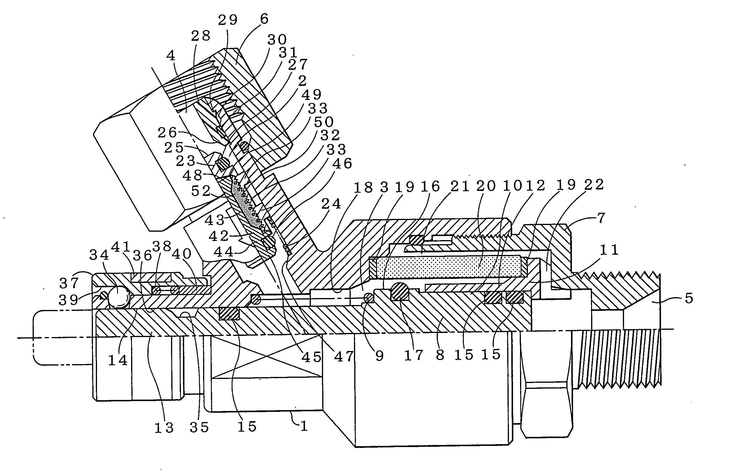
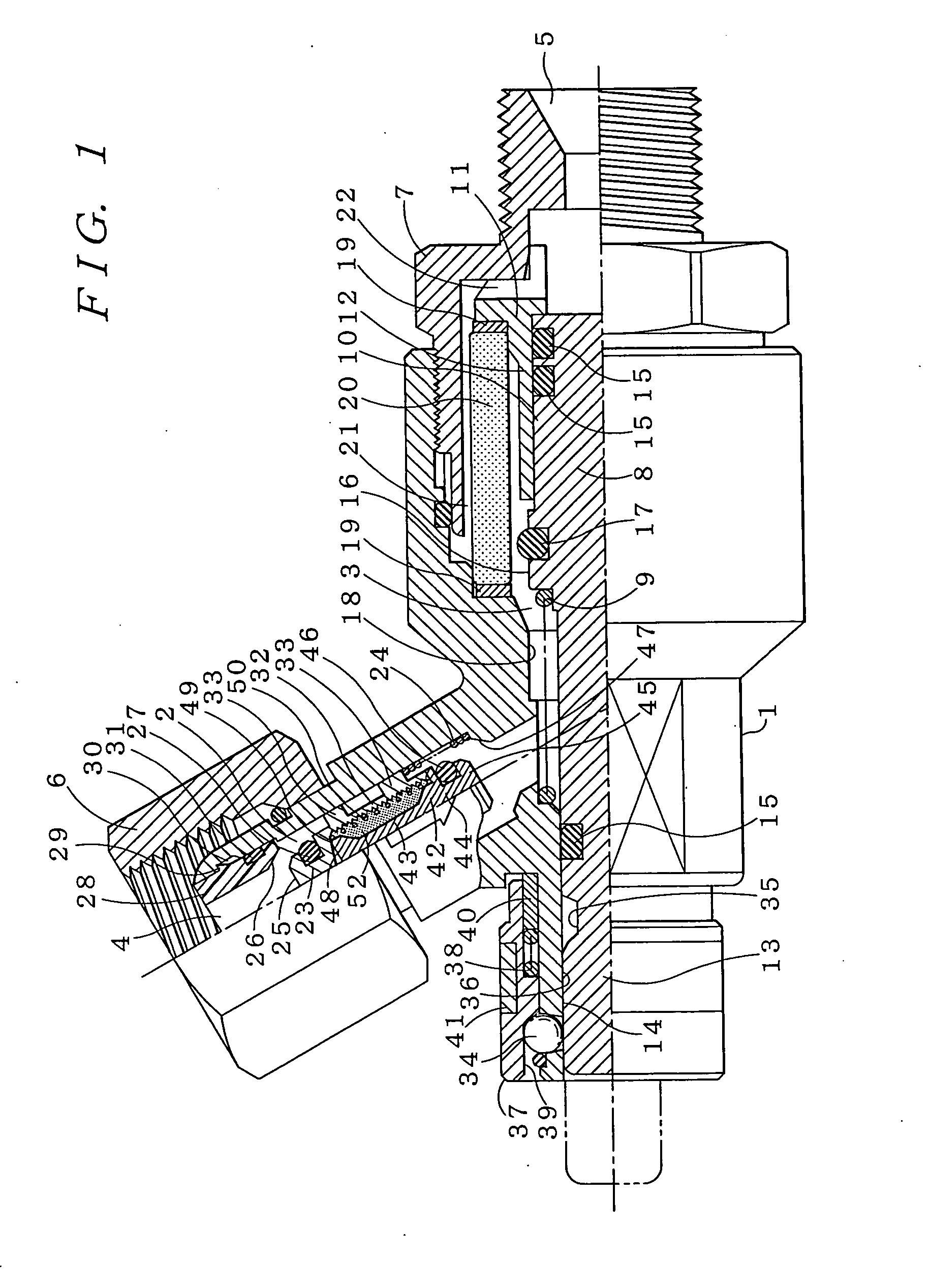
[0016]FIG. 1 shows an embodiment of a dry safety device for an inflammable gas according to the present invention. The dry safety device has a case main body (1) having therein a gas passage comprised of a first passage (2) and a second passage (3) which extends in a direction crossing the first passage (2). The first passage (2) has an inlet end terminating in a primary side open port (4) for connection to a supply source of inflammable gas, and the second passage (3) has an outlet end terminating in a secondary side open port (5) for connection to a burner torch. Around the primary side open port (4) of the case main body (1), a cap nut (6) is provided for detachable connection to a hose or the like which communicates to a source of pressurized inflammable gas, such as a bomb (not shown). On the secondary side of the case main body (1), a secondary side main body (7) having the secondary side open port (5) is screwed, and a secondary side gas-fired appliance such as a burner torch...


PUM


Abstract

A dry safety device for an inflammable gas comprises a case main body having a gas passage which terminates at one end in a primary side open port connectable to a source of inflammable gas and terminates at the other end in a secondary side open port connectable to a gas-fired appliance. A spindle undergoes sliding movement in the case main body between an open position for opening the gas passage and a closed position for closing the gas passage, and a spindle spring normally urges the spindle to the open position and permits the spindle to move to the closed position in response to a counter-flow pressure exerted on the spindle by a counter flow of inflammable gas directed from the secondary side open port to the primary side open port. A flame-extinguishing filter disposed in the gas passage extinguishes a back fire that may occur during a counter flow of inflammable gas, and a normally open shutoff valve disposed in the gas passage upstream from the filter closes the gas passage when an ambient temperature exceeds a given value.

Description

BACKGROUND OF THE INVENTION [0001] 1. Technical Field of the Invention [0002] The present invention relates generally to a dry safety device for an inflammable gas, and more particularly to a dry safety device for shutting off a gas passage to prevent adverse effects to the supply source of inflammable gas when a dangerous condition such as back fire or fire occurs during a gas welding operation or a gas cutting operation. [0003] 2. Description of Related Art [0004] As a safety measure in gas welding or gas cutting operations using an inflammable gas, it is known to provide a dry gas safety device having a gas passage shutoff mechanism to prevent a counter flow or backflow of the inflammable gas accompanied with back fire that may occur in a hose connecting a burner torch to a bomb filled with the inflammable gas. Such a dry safety device is constructed so that when a counter flow of gas occurs from a secondary side toward a primary side, the device is automatically operated by the ...

Claims


Application Information

Patent Timeline
Patent Type & Authority Applications(United States)
IPC IPC(8): F16K15/02A62C2/04F16K17/34F16K17/38F16K51/00F23D14/46F23D14/82F23K5/00F23N5/24
CPCF16K17/383F23D14/825F23D14/465Y10T137/7843Y10T137/7724Y10T137/1819Y10T137/1963
Inventor ABE, MASAYUKI
Owner SANKI CO LTD
Learn More