Rotating pneumatic knee joint structure
a knee joint and pneumatic technology, applied in the field of knee joint structure, can solve the problems of pain in the rear section of the muscle, and the inability of conventional artificial knee joint structure to be adjusted to withstand the weight of the user,
- Summary
- Abstract
- Description
- Claims
- Application Information
AI Technical Summary
Benefits of technology
Problems solved by technology
Method used
Image
Examples
Embodiment Construction
[0015] The following descriptions are of exemplary embodiments only, and are not intended to limit the scope, applicability or configuration of the invention in any way. Rather, the following description provides a convenient illustration for implementing exemplary embodiments of the invention. Various changes to the described embodiments may be made in the function and arrangement of the elements described without departing from the scope of the invention as set forth in the appended claims.
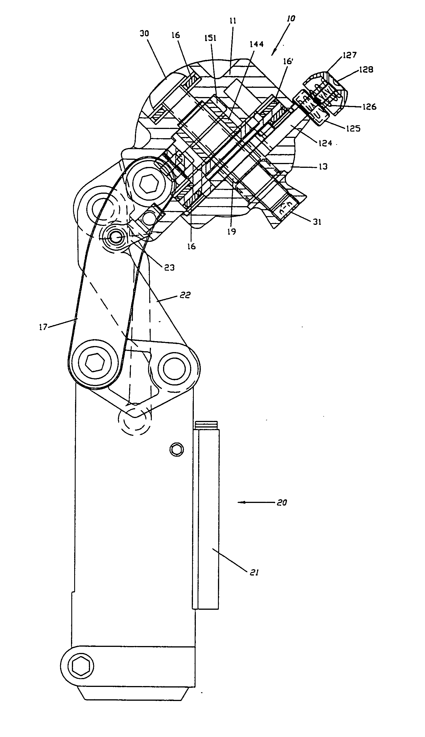
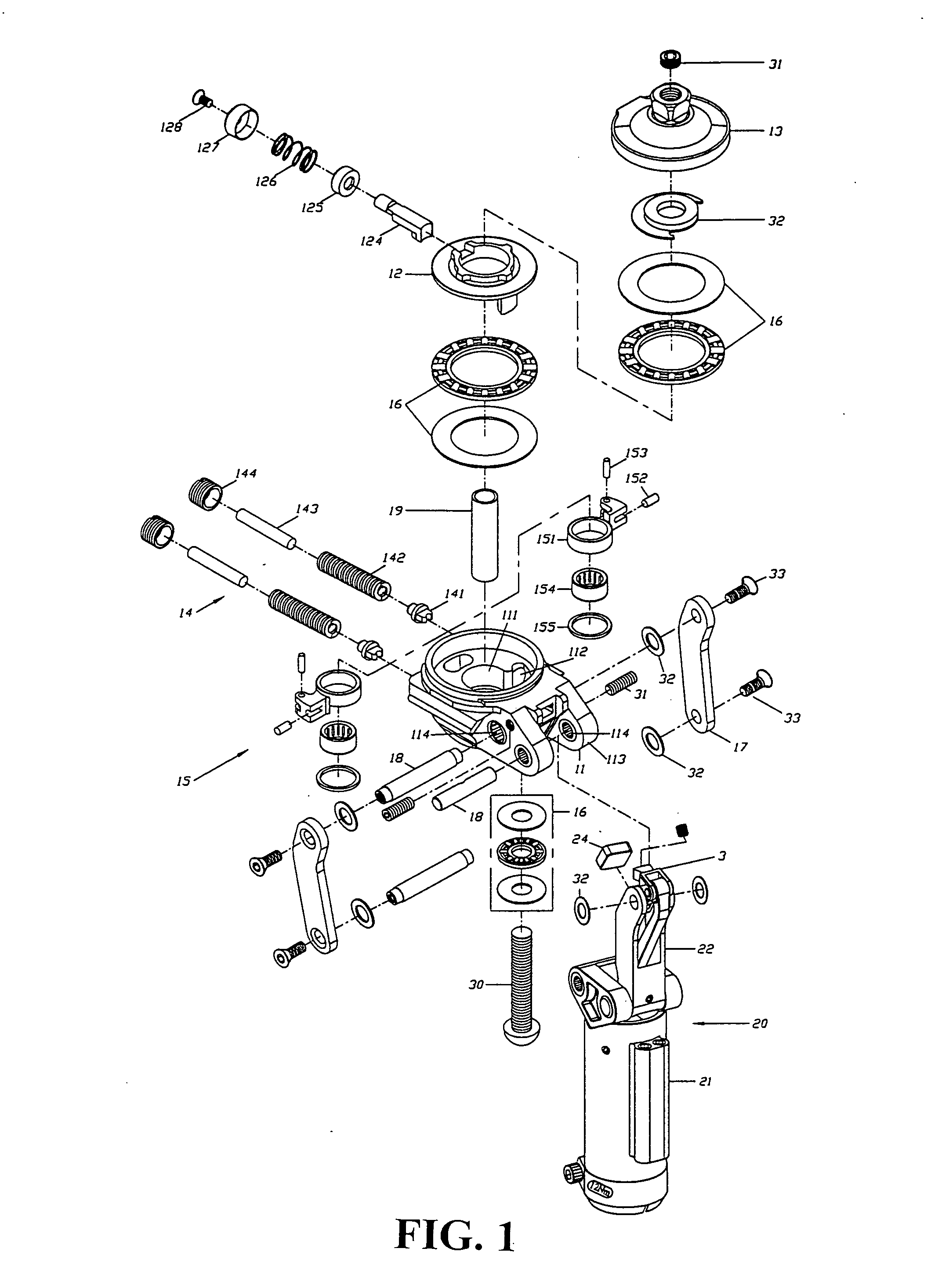
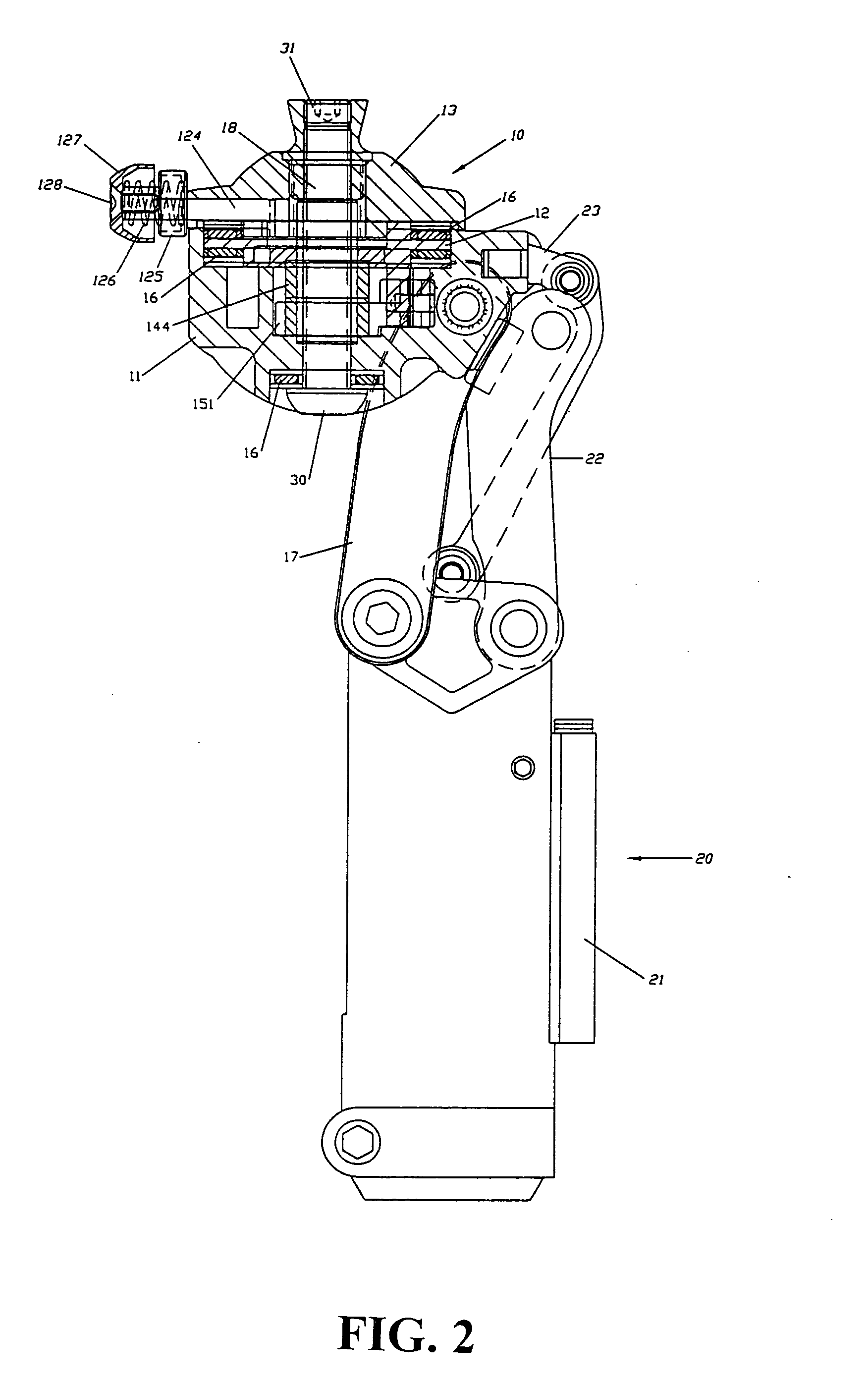
[0016] Referring to FIGS. 1 to 4A and 4B, there is shown a rotating pneumatic knee joint structure comprising a twisting connector module 10 and a pneumatic body module 20. The twisting connector module 20 includes a twisting connector 11, a rotating seat 12, an adjustable rotating upper seat 13, adjustable screws module 14 including spring support 141, spring 142, spring leaf 143 and adjustable screws 144, two rotating block module 15 including a rotating block 151, a spring block 152, an axle...
PUM
 Abstract
Description
Claims
Application Information
 - R&D Engineer
- R&D Manager
- IP Professional
- Industry Leading Data Capabilities
- Powerful AI technology
- Patent DNA Extraction
Browse by: Latest US Patents, China's latest patents, Technical Efficacy Thesaurus, Application Domain, Technology Topic, Popular Technical Reports.
© 2024 PatSnap. All rights reserved.Legal|Privacy policy|Modern Slavery Act Transparency Statement|Sitemap|About US| Contact US: help@patsnap.com


