
Bionic knee joint structure based on tensegrity structure, and control method design

A technology of tensegrity structure and control method, applied in prosthesis, medical science, artificial leg, etc., can solve the problems of not considering the dynamic model of the tensegrity structure, complex structure, etc.

Active Publication Date: 2021-10-19
CHANGCHUN UNIV OF TECH
View PDF6 Cites 0 Cited by
  • Summary
  • Abstract
  • Description
  • Claims
  • Application Information

AI Technical Summary

Problems solved by technology

However, due to the complexity of the structure, the dynamic model and control method design of the tensegrity structure were not considered in the design of these two tensegrity bionic structures. In addition, the two bionic structures did not consider noise conditions such as mechanical structure errors. , Mechanical vibration, friction between components, feedback signal noise, external static friction and other factors under the operation of the tensioned bionic structure

Method used


Image

  • Bionic knee joint structure based on tensegrity structure, and control method design
  • Bionic knee joint structure based on tensegrity structure, and control method design
  • Bionic knee joint structure based on tensegrity structure, and control method design

Examples


Embodiment Construction

[0050] Below in conjunction with embodiment and accompanying drawing, the present invention will be further described:

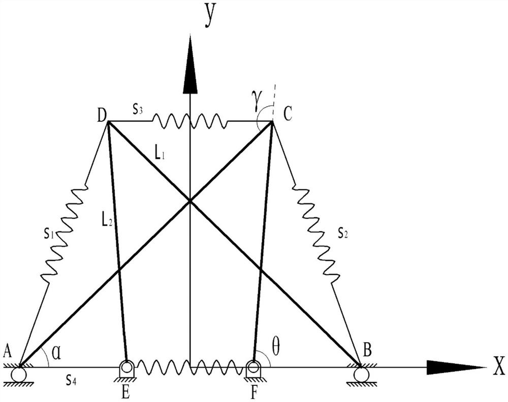
[0051] figure 1 is a geometric structure diagram of a bionic knee joint structure based on a tensegrity structure, such as figure 1 As shown, the structure is specifically as follows:

[0052] S1: The geometric structure of the bionic knee joint structure is as follows:

[0053] S101: The overall structure of the bionic knee joint tension is composed of four rods and four sets of ropes. In the bionic knee joint structure, the rods AC and BD can be regarded as bone structures simplified from the femur, tibia, and fibula, respectively. Rods CF and DE can be viewed as structures with the same function simplified from the patella and nearby tissues. For a two-bar linkage, the lengths of rods AC and CF are L 1 and L 2 , where L 1 greater than L 2 . Similarly, another group of two-link mechanism BD-DE and two-link structure AC-CF are symmetrical about the...


PUM


Abstract

The invention discloses a bionic knee joint structure based on a tensegrity structure, and a control method design. The bionic knee joint structure based on the tensegrity structure is designed by aiming at the rehabilitation problem of the knee joint of a human body and combining the rigid-flexible coupling characteristic of the tensegrity structure on the basis of the bionics principle. And an anti-noise return-to-zero neural network model is designed as a control method. In the building process of the bionic knee joint structure, the following points are considered: a, according to different functions borne by tissues such as muscles, simplifying ligaments and bones of the knee joint of a human body, the tissues with the same functions into rope and rod structures, so as to simplify the knee joint of the human body; b, analyzing kinematic characteristics of the bionic knee joint structure, and establishing a kinetic model; c, considering the limiting function when the knee joint is straightened, realizing the limiting function of the bionic knee joint structure under the action of external force through a connecting rod structure; and d, considering the human knee joint moment in the dynamic model, and reflecting the influence of knee joint movement on the bionic knee joint structure.

Description

technical field [0001] The invention relates to the fields of tensegrity integral structure, knee joint bionics and bionic structure, and relates to the design of a bionic knee joint structure and control method based on the tensegrity integral structure. Background technique [0002] The tensegrity structure has the characteristics of shape adjustability, force controllability, rope tensile strength and structural lightness, etc., which play an important role in the field of bionics. In the process of rehabilitation training, due to symptoms such as lower limb hemiplegia and limb movement incoordination caused by stroke, the rehabilitation training activities of human lower limb joints, especially knee joints, become very important. The human knee joint is composed of many bones, muscles and ligaments, so the knee joint can be regarded as a rigid-flexible coupling structure. Therefore, from the perspective of bionics, the knee joint structure cannot be simply mapped to the...

Claims


Application Information

Patent Timeline
Patent Type & Authority Applications(China)
IPC IPC(8): A61F2/64A61F2/70
CPCA61F2/64A61F2/68A61F2002/704
Inventor 孙中波赵立铭刘克平王刚段晓琴易江衡焘韬
Owner CHANGCHUN UNIV OF TECH
Learn More