Motor
a technology of motors and motors, applied in the field of motors, can solve the problems of high noise level, high degree of accuracy, weak ball bearing structure, etc., and achieve the effect of reducing noise from the motor, increasing the lifetime, and reducing the noise of the motor
- Summary
- Abstract
- Description
- Claims
- Application Information
AI Technical Summary
Benefits of technology
Problems solved by technology
Method used
Image
Examples
first embodiment
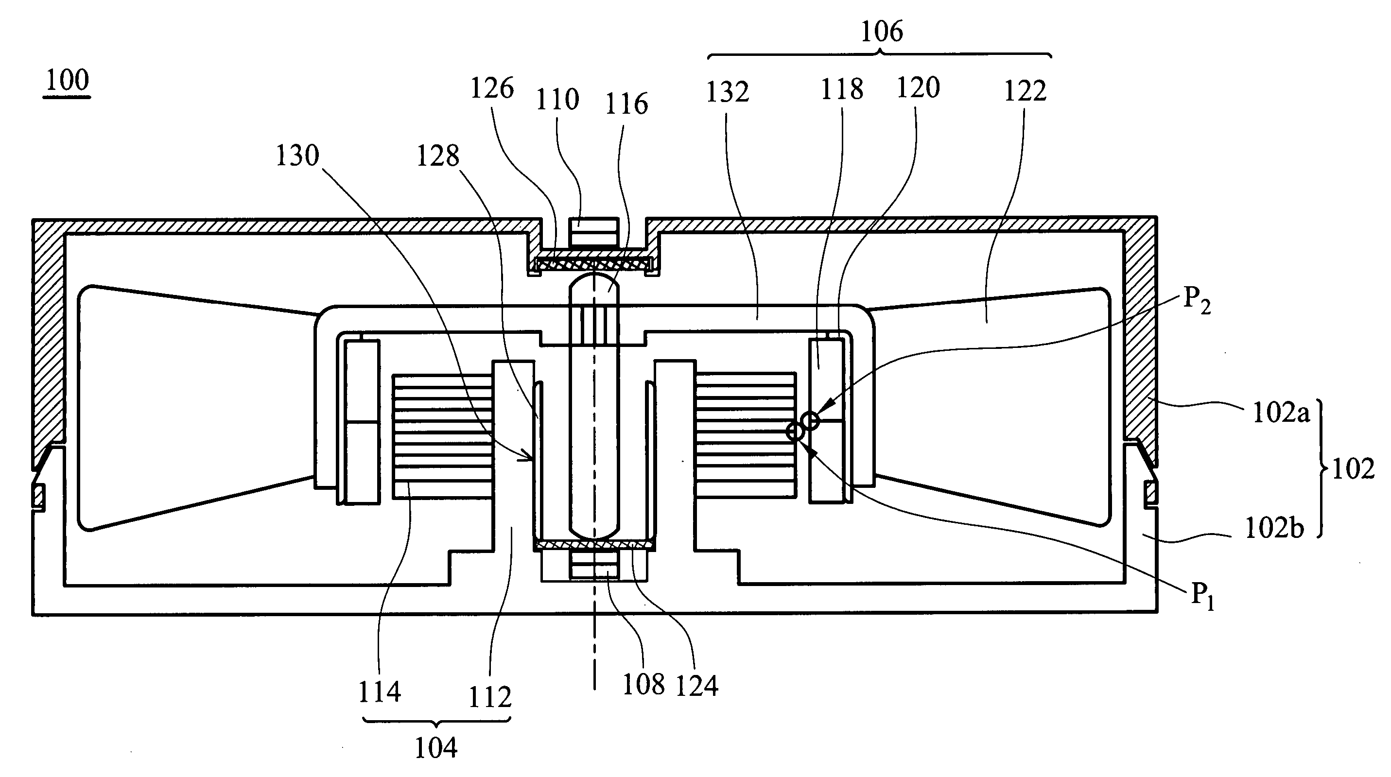
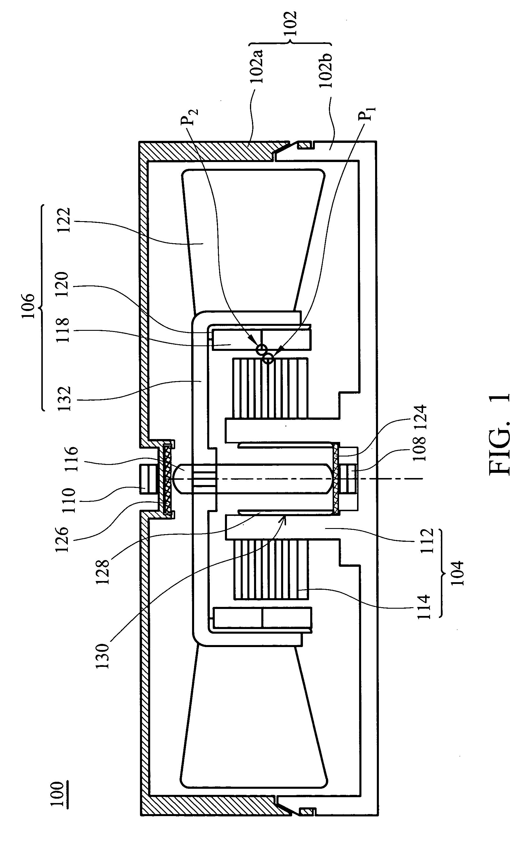
[0027]FIG. 1 is a schematic diagram of a motor according to the present invention. The motor 100 comprises a frame 102, a stator 104, a rotor 106, and magnetic structures 108 and 110. The magnetic structures 108 and 110 are attracted to each other by magnetic force. A shaft 116 extends axially from the rotor 106. The shaft 116 and the magnetic structures 108 and 110 are aligned coaxially. In the motor 100, the magnetic attraction generated between the magnetic structures 108 and 110 attracts the shaft 116 such that the rotor 106 is fixed between the magnetic structures 108 and 110.
[0028] The frame 102 protects the motor 100 and internal elements thereof from external force. The frame 102 is either integrally formed or comprises an upper and a lower cover 102a and 102b. The frame 102 may also be formed by a plurality of divided portions (not shown). The covers 102a and 120b are connected by fitting, engaging, gluing, locking, or connecting via a cushion device. Furthermore, the upper...
third embodiment
[0043]FIG. 4 is a schematic diagram of a motor 300 according to the present invention, from which elements common to said embodiments are omitted. The difference is that a magnetic structure 304 is disposed on the top of the stator fixing base 112, and a magnetic structure 302 is formed on the rotor hub 132. The magnetic structures 302 and 304 are attracted to each other without making contact. The magnetic structure 304 does not contact the permeable structure 114 and is positioned higher than the permeable structure 114 in an axial direction. The magnetic structure 302 is a circular, fan-shaped, block-shaped, or rectangular structure. The shape and position of the magnetic structure 302 correspond to those of the magnetic structure 304.
[0044] Furthermore, the magnetic structure 304 and the stator fixing base 112 are connected by gluing, fitting, engaging, contacting, or combinations thereof. The magnetic structure 302 and the rotor hub 132 are also connected by gluing, fitting, en...
fourth embodiment
[0045]FIG. 5 is a schematic diagram of a motor 400 according to the present invention, from which elements common to said embodiments are omitted. The difference is that there is only one magnetic structure 402 formed on an upper cover 102a of the frame 102. The magnetic central plane P2 of the magnetic structure 118 is lower than the magnetic central plane P1 of the permeable structure 114 in an axial direction. Moreover, a wear-resistant structure 408 is disposed at a lower cover 102b. The contact point between the shaft 116 and the wear-resistant structure 408 is slightly higher or lower than, or level with the magnetic central plane P1.
[0046] In this embodiment, the magnetic structure 402 is entirely made of a magnetic material, or formed by a wear-resistant structure 406 and a magnetic body 404. Moreover, the surface between the magnetic structure 402 and the shaft 116, the surface between the wear-resistant structure 406 and the shaft 116, and / or the surface between the wear-r...
PUM
 Abstract
Description
Claims
Application Information
 - R&D
- Intellectual Property
- Life Sciences
- Materials
- Tech Scout
- Unparalleled Data Quality
- Higher Quality Content
- 60% Fewer Hallucinations
Browse by: Latest US Patents, China's latest patents, Technical Efficacy Thesaurus, Application Domain, Technology Topic, Popular Technical Reports.
© 2025 PatSnap. All rights reserved.Legal|Privacy policy|Modern Slavery Act Transparency Statement|Sitemap|About US| Contact US: help@patsnap.com


