Operation lever device of construction machinery and construction machinery
- Summary
- Abstract
- Description
- Claims
- Application Information
AI Technical Summary
Benefits of technology
Problems solved by technology
Method used
Image
Examples
first embodiment
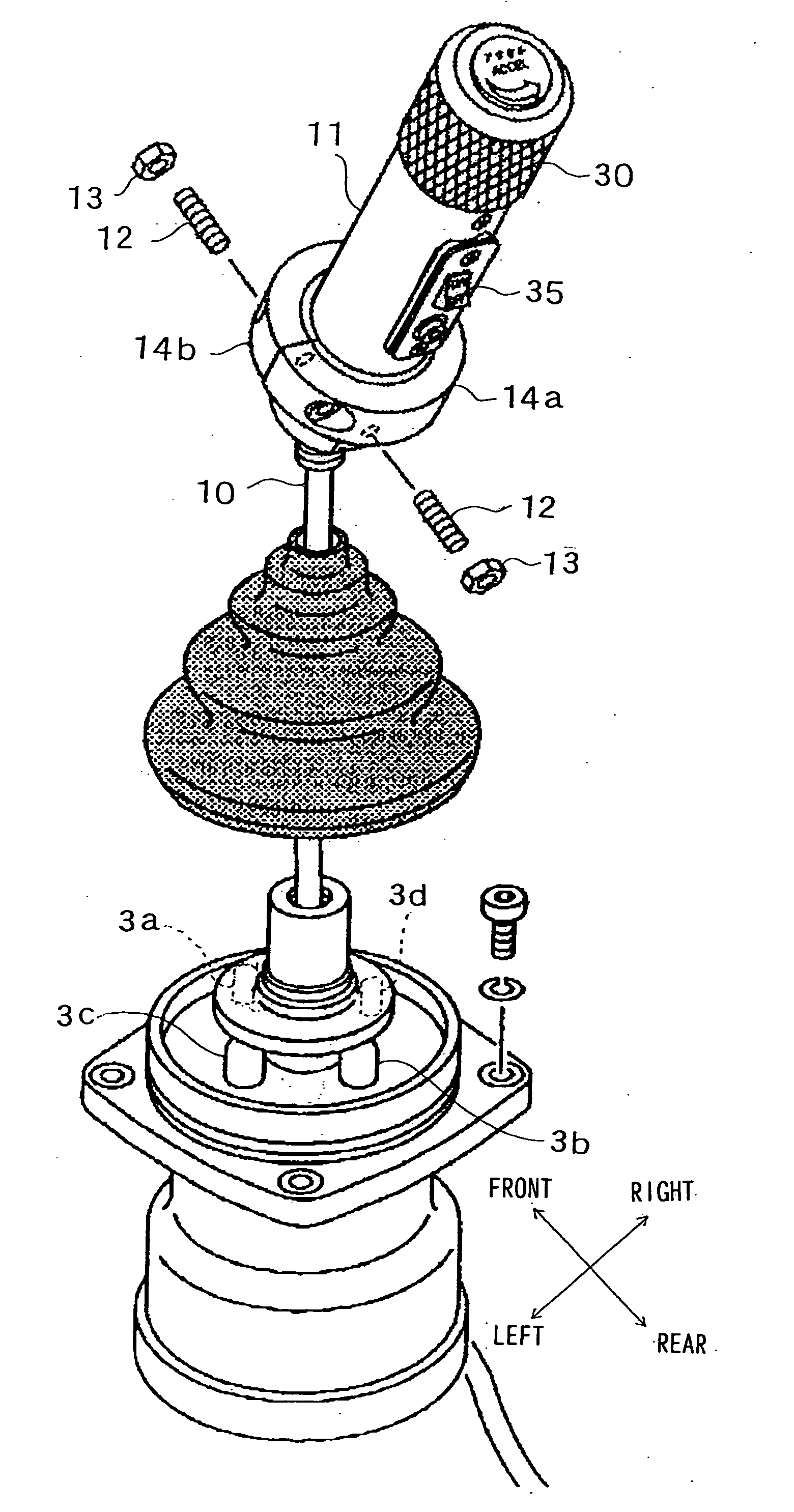
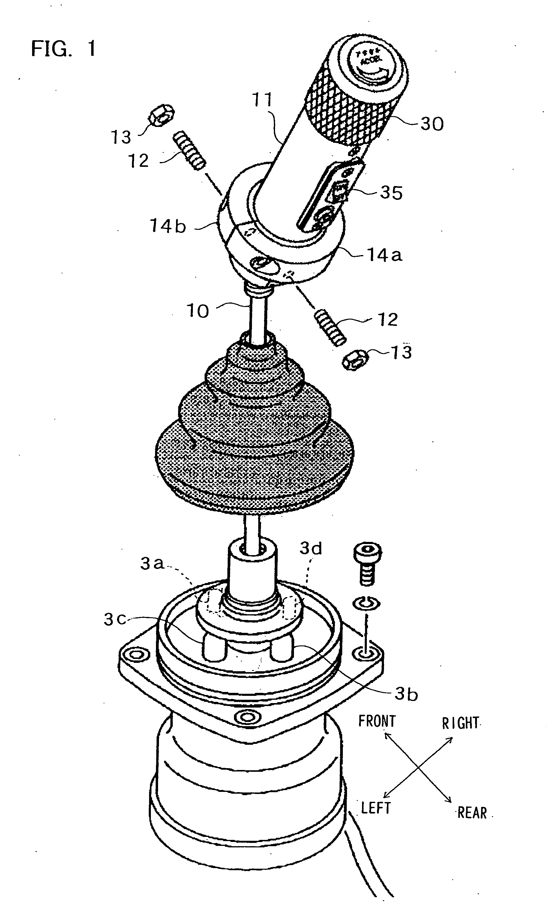
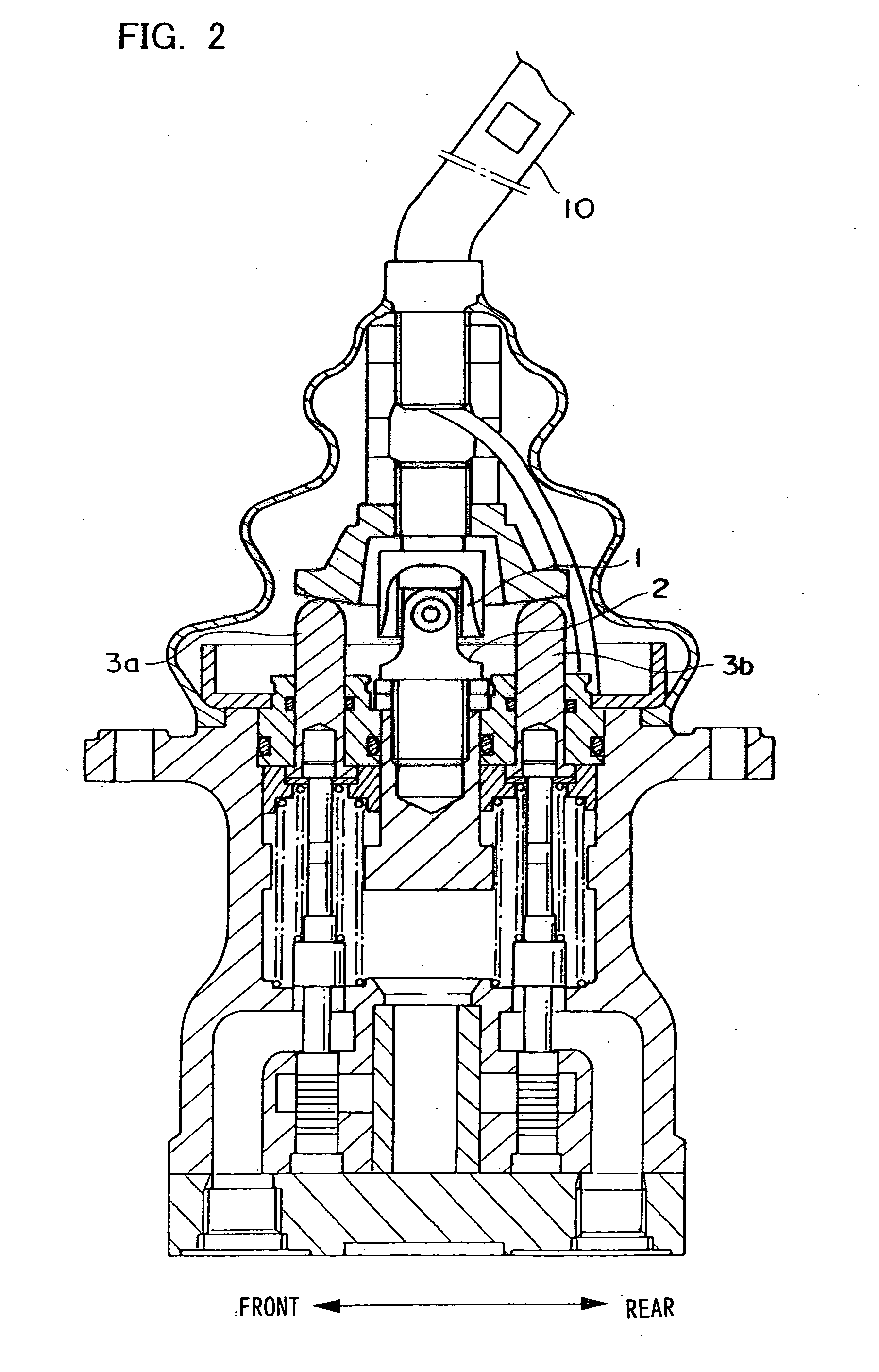
[0041] The first embodiment of the present invention is now explained in reference to FIGS. 1 to 8. FIG. 8 is a side elevation of a crawler crane in which operating levers 10 achieved in the first embodiment of the present invention are employed. As shown in FIG. 8, the crawler crane includes a traveling structure or a traveling body 61, a revolving superstructure or a revolving body 63 mounted on the traveling structure 61 so as to be allowed to rotate via a swinging device 62 and a boom 64 supported at the revolving superstructure 63 so as to be allowed to be hoisted up / down. At the revolving superstructure 63, a hoist drum 65, a main hoist drum 66 and an auxiliary hoist drum 67 are mounted. As the main hoist drum 66 is driven, a main hoisting cable 66a is taken up / delivered to move a main hook 68 up / down. As the auxiliary hoist drum 67 is driven, an auxiliary hoisting cable 67a is taken up / delivered to move an auxiliary hook 69 up / down. In addition, as the boom hoist drum 65 is d...
example 1
VARIATION EXAMPLE 1 OF THE FIRST EMBODIMENT
[0065] Only the signal from one of the rotary operating members 30L and 30R at the left lever 10L and the right lever 10R may be used as a valid signal. For instance, either the lever 10L or the lever 10R may be selected in accordance with the operator's preference to implement the engine speed control by using the rotation speed command value reflecting the operation of the rotary operating member at the selected lever. FIG. 10 presents a conceptual diagram of this engine speed control.
[0066] As shown in FIG. 10, the rotation speed command value from the left lever rotary operating member 30L and the rotation speed command value from the right lever rotary operating member 30R are both input to a switching circuit 50B. The switching circuit 50B, which is switched in response to an operation of a selector switch 102, outputs the command value from the rotary operating member 30L at the left lever 10L or the rotary operating member 30R at t...
example 2
VARIATION EXAMPLE 2 OF THE FIRST EMBODIMENT
[0068] The direction along which the left rotary operating member 30L is operated to increase the engine speed may be reversed from the direction along which the right rotary operating member 30R is operated to increase the engine speed. FIG. 11 presents a conceptual diagram of a control implemented to switch the engine speed command in conformance to the direction along which a given rotary operating member 30 is operated. It is assumed that when the rotary operating member 30 is operated counterclockwise, the level of the voltage indicated by the voltage signal output by the rotary operating member 30 increases.
[0069] As shown in FIG. 11, the voltage signal from the rotary operating member 30 is input to a switching circuit 50C. A switch occurs from a contact point A to a contact point B or vice versa in response to an operation of a selector switch 103. A function generator 50D is connected to the contact point A of the switching circui...
PUM
 Abstract
Description
Claims
Application Information
 - R&D
- Intellectual Property
- Life Sciences
- Materials
- Tech Scout
- Unparalleled Data Quality
- Higher Quality Content
- 60% Fewer Hallucinations
Browse by: Latest US Patents, China's latest patents, Technical Efficacy Thesaurus, Application Domain, Technology Topic, Popular Technical Reports.
© 2025 PatSnap. All rights reserved.Legal|Privacy policy|Modern Slavery Act Transparency Statement|Sitemap|About US| Contact US: help@patsnap.com


