
System for performing anastomosis

Inactive Publication Date: 2005-02-10
AESCULAP AG
View PDF99 Cites 53 Cited by
  • Summary
  • Abstract
  • Description
  • Claims
  • Application Information

AI Technical Summary

Benefits of technology

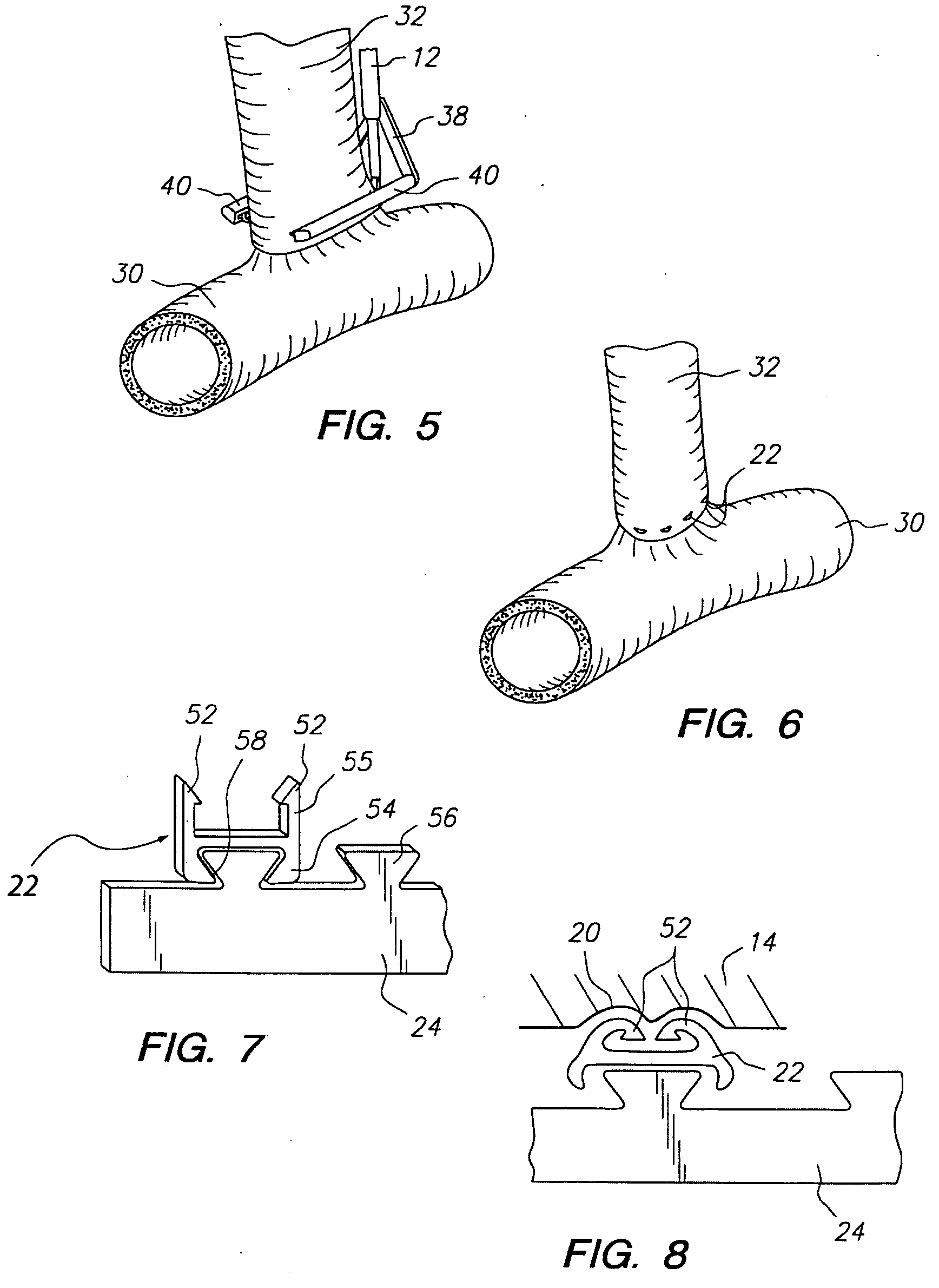
[0009] In another aspect of the invention, a stapling system for use in performing anastomosis between a graft vessel and a target vessel includes staples having ends configured to be inserted through tissue and bent over to secure the tissue, a staple strip holding the staples in a spaced arrangement for insertion into the tissue as a row of staples, and a frangible portion provided between each staple and the staple strip allowing the staples to be separated from the staple strip after insertion.
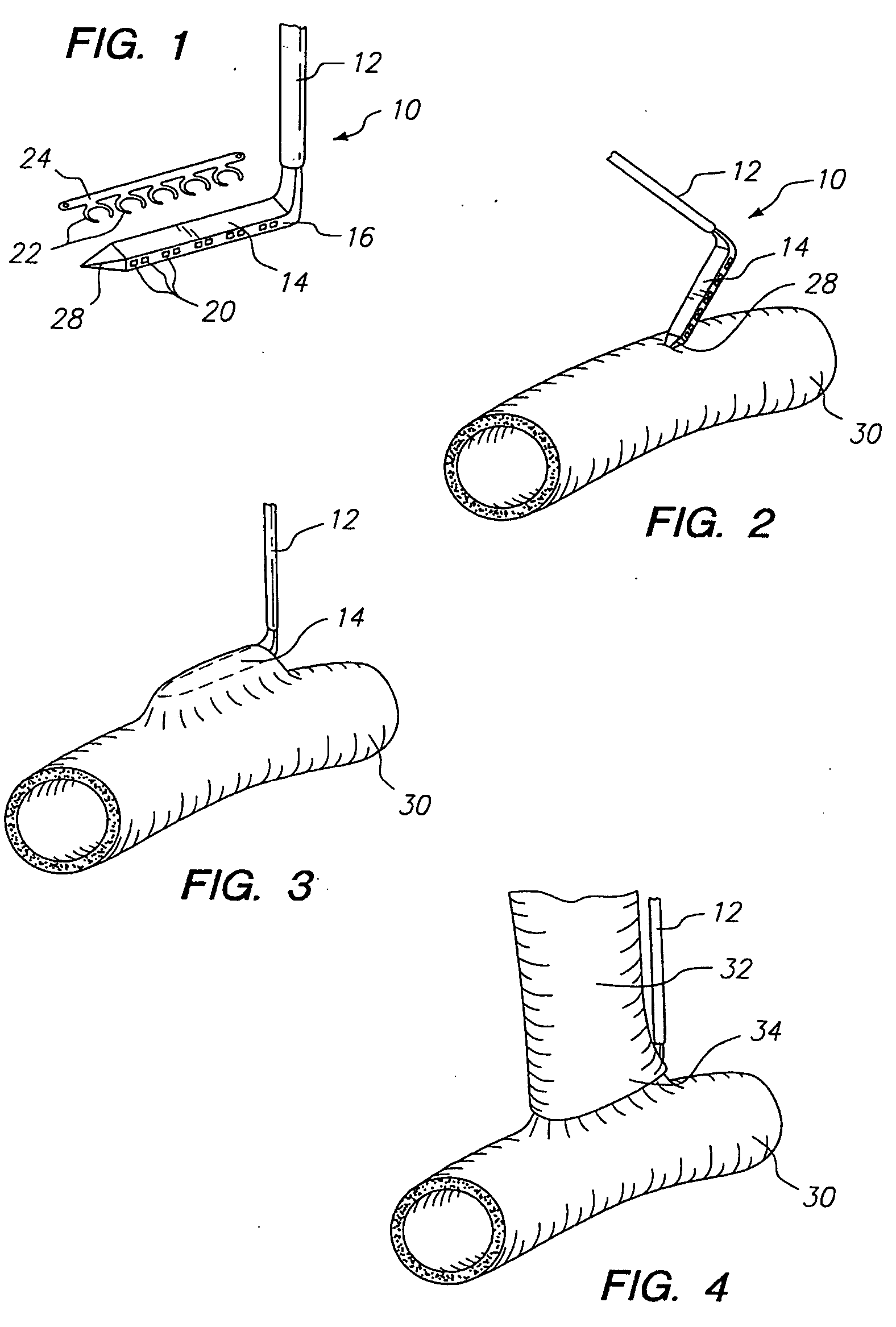
[0013] In another aspect of the invention, the anvil arm is inserted into the target vessel at a location spaced apart from an anastomosis site. Thus, the cutter performs an arteriotomy at a location spaced apart from the entry point of the anvil arm into the target vessel. The end of the graft vessel is placed against the side of the target vessel, such that the perimeter of the end of the graft vessel defines a closed area on the wall of the target vessel. The arteriotomy is performed within that closed area on the graft vessel, in order to reduce or prevent leakage between the graft vessel and the target vessel. In this way, a tissue bridge is formed between the arteriotomy within the anastomosis and the point on the target vessel at which the anvil is inserted. Alternately, the anvil arm may be inserted into the graft vessel.
[0014] In another aspect of the invention, the cutter and / or the anvil arm includes one or more safety features to prevent the cutter from moving until the staple holder is in place. When in place, the staple holder engages the cutter and / or anvil arm, freeing the cutter to move relative to the anvil arm. In this way, premature deployment of the cutter is prevented.

Problems solved by technology

The suturing process is a time consuming and difficult procedure requiring a high level of surgical skill.
This suturing requires a high degree of precision and is quite time consuming.
The use of a side clamp or similar device can cause emboli to detach from the wall of the aorta and enter the bloodstream, which is undesirable.

Method used


Image

  • System for performing anastomosis
  • System for performing anastomosis
  • System for performing anastomosis

Examples


Embodiment Construction

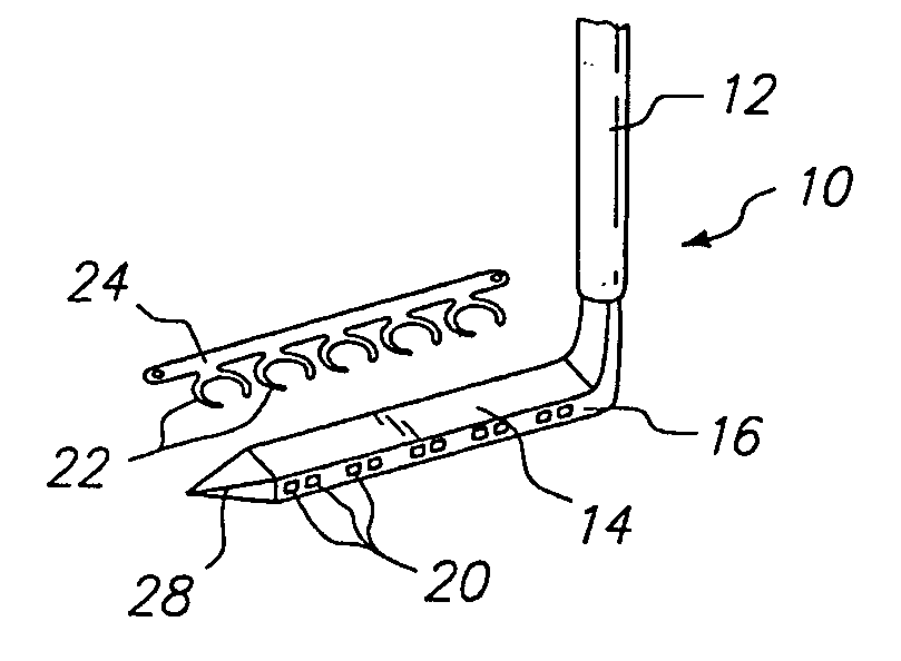
[0066] As shown in FIG. 1, one embodiment of an anvil 10 includes a handle 12 and an anvil arm 14 extending from the handle 12. The anvil arm 14 may be oriented substantially perpendicular to the handle 12, or oriented at a different angle. The anvil arm 14 may be provided with one or more staple bending features 16 on opposite sides of the anvil arm 14. In the anvil 10 shown in FIG. 1, the staple bending features 16 each include a plurality of recesses 20 which receive the ends of staples 22 and cause the staple ends to bend over. At least one of the staple bending features 16 may be configured differently or omitted, if desired. The staples 22 may be connected to a staple holding strip 24. The staples 22 are U-shaped and are arranged in a spaced apart parallel configuration such that the staples 22 all lie in a single plane. Alternately, the staples 22 may be shaped differently, and / or lie in one or more different planes. An exemplary anvil arm 14 has a height and a width of about...


PUM


Abstract

An anastomosis system for connecting a graft vessel to a target vessel includes spaced-apart arms, and an anvil connected to those arms, where that anvil has a blunt distal end. The anvil is insertable into the target vessel. One or more connectors, such as staples, may be deployed from each arm to connect the graft vessel to the target vessel.

Description

[0001] This application is a continuation of U.S. patent application Ser. No. 10 / 151,441, filed on May 20, 2002, which in turn is a continuation-in-part of U.S. Pat. No. 6,391,038, both of which are incorporated by reference in their entirety.FIELD OF THE INVENTION [0002] The invention relates to an apparatus and method for performing anastomosis. BACKGROUND [0003] Anastomosis is a procedure by which two hollow tissue structures are joined together. More particularly, vascular anastomosis is a procedure by which two blood vessels within a patient are surgically joined together. Vascular anastomosis is performed during treatment of a variety of conditions including coronary artery disease, diseases of the great and peripheral vessels, organ transplantation, and trauma. In coronary artery disease (CAD) an occlusion or stenosis in a coronary artery interferes with blood flow to the heart muscle. Treatment of CAD involves the grafting of a vessel in the form of a prosthesis or harvested...

Claims


Application Information

Patent Timeline
IPC IPC(8): A61B17/00A61B17/04A61B17/072A61B17/11A61B17/115A61B17/122A61B19/00A61F2/06
CPCA61B17/0469A61B17/072A61B17/1152A61B17/122A61B2017/00243A61F2/064A61B2017/07285A61B2017/1107A61B2017/1135A61B2019/307A61B2017/07214A61B2090/037
Inventor BOMBARD, DAVID L.KNODEL, BRYAN D.VARGAS, JAIME S.HENDRICKSEN, MICHAEL J.YENCHO, STEPHEN A.NIELSEN, JAMES T.HAUSEN, BERNARD A.DONOHOE, BRENDAN M.BENDER, THEODORE M.
Owner AESCULAP AG
Learn More