System and method for automatically correcting duty cycle distortion
a technology of automatic correction and duty cycle, applied in the direction of digital transmission, pulse automatic control, transmission, etc., can solve the problems of duty cycle distortion in an optical driver or receiver circuit, common problem in many optical driver and receiver circuits,
- Summary
- Abstract
- Description
- Claims
- Application Information
AI Technical Summary
Benefits of technology
Problems solved by technology
Method used
Image
Examples
Embodiment Construction
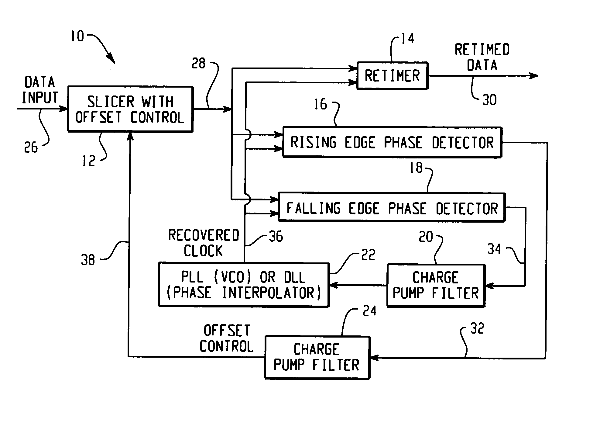
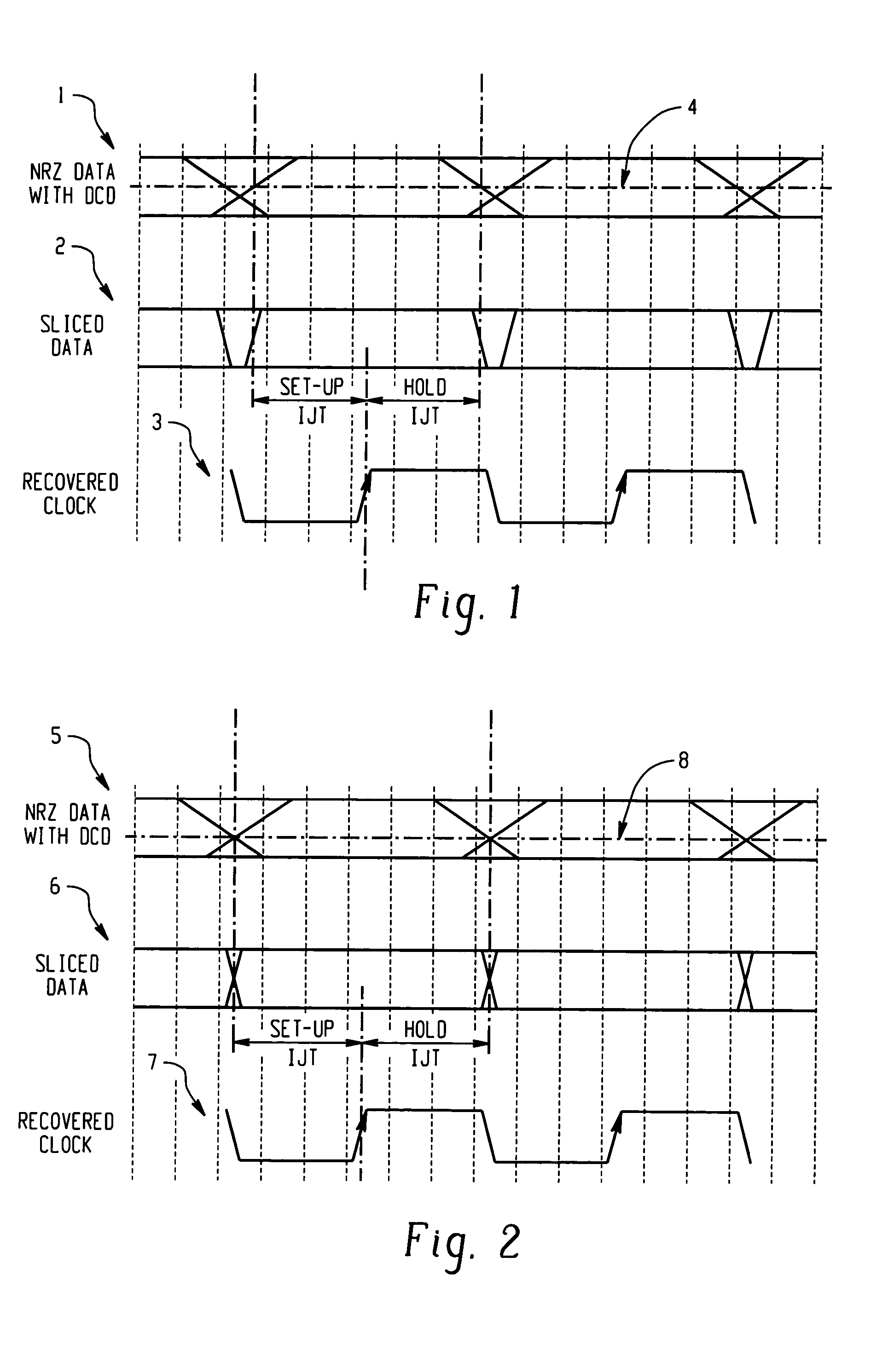
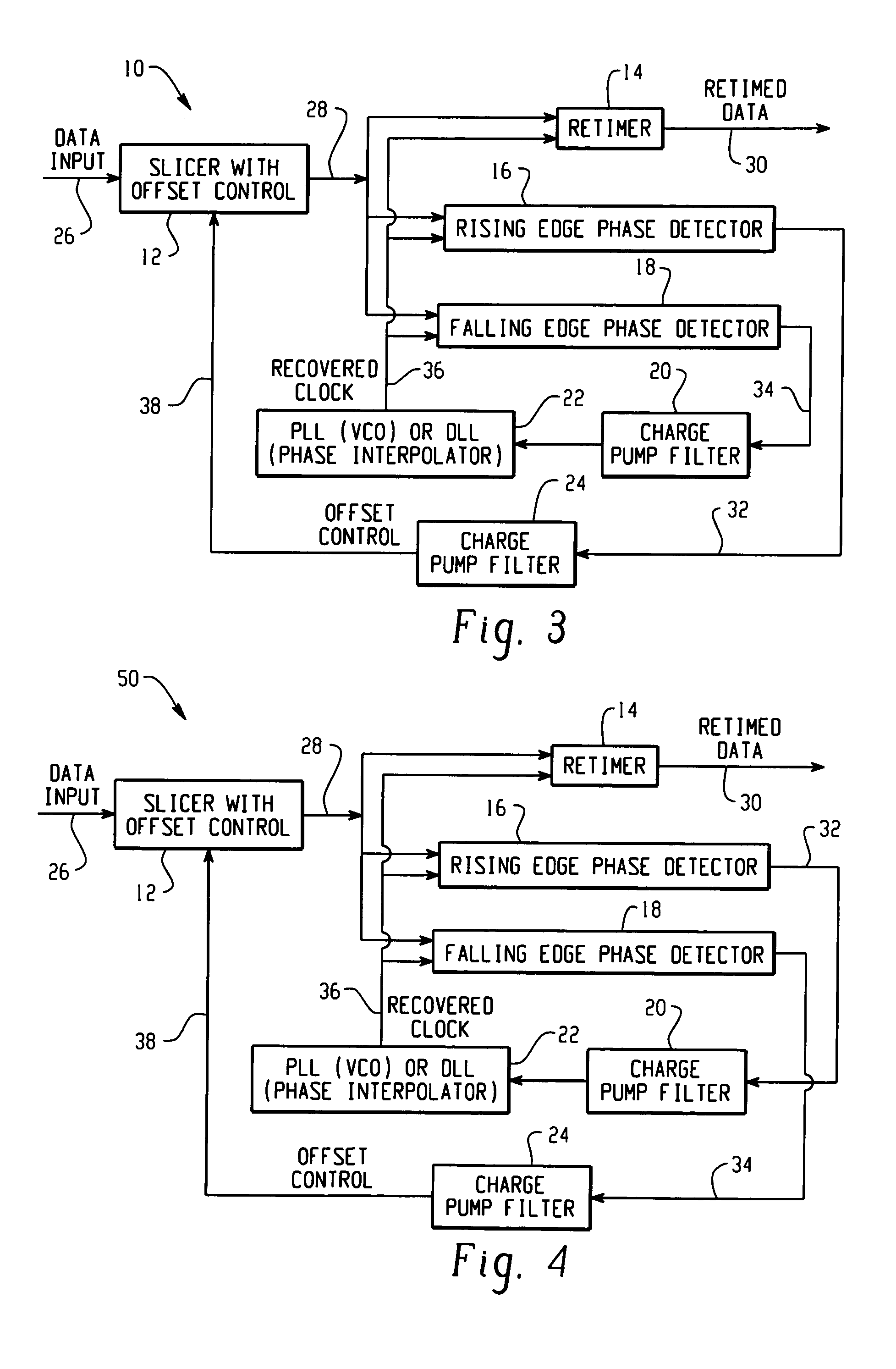
[0012] With reference now to the drawing figures, FIGS. 1 and 2 are timing diagrams illustrating a method for correcting duty cycle distortion in a clock and data recovery system. FIGS. 1 and 2 both illustrate an eye pattern for a typical data input signal 1, 5 received by a clock and data recovery system. Also shown are a sliced data input signal 2, 6 and a recovered clock signal 3, 7. In a typical clock and data recovery circuit, a slicer (e.g., a limiting amplifier) may be used to horizontally slice the data input signal 1, 5 at a pre-selected slicer offset voltage 4, 8. A recovered clock signal 3, 7 is then typically aligned in order to sample the resulting sliced data signal 2, 6. (See, e.g., FIG. 3-5)
[0013]FIG. 1 illustrates a typical default setting for the slicer offset voltage 4. For example, in the case of a differential AC coupled data input signal 1, the default slicer offset voltage 4 will typically be at a zero potential. However, as a result of duty cycle distortion ...
PUM
 Abstract
Description
Claims
Application Information
 - R&D
- Intellectual Property
- Life Sciences
- Materials
- Tech Scout
- Unparalleled Data Quality
- Higher Quality Content
- 60% Fewer Hallucinations
Browse by: Latest US Patents, China's latest patents, Technical Efficacy Thesaurus, Application Domain, Technology Topic, Popular Technical Reports.
© 2025 PatSnap. All rights reserved.Legal|Privacy policy|Modern Slavery Act Transparency Statement|Sitemap|About US| Contact US: help@patsnap.com


