
Prosthetic valve devices and methods of making such devices

a technology of prosthetic valves and valves, applied in the field of medical devices, can solve the problems of loss of effectiveness, physical manifestations and pathology, and the insufficientness of venous valves, and achieve the effect of reducing the risk of venous valve failure, reducing the effectiveness of venous valves, and improving the quality of venous valves

Active Publication Date: 2005-02-03
COOK MEDICAL TECH LLC
View PDF28 Cites 549 Cited by
  • Summary
  • Abstract
  • Description
  • Claims
  • Application Information

AI Technical Summary

Benefits of technology

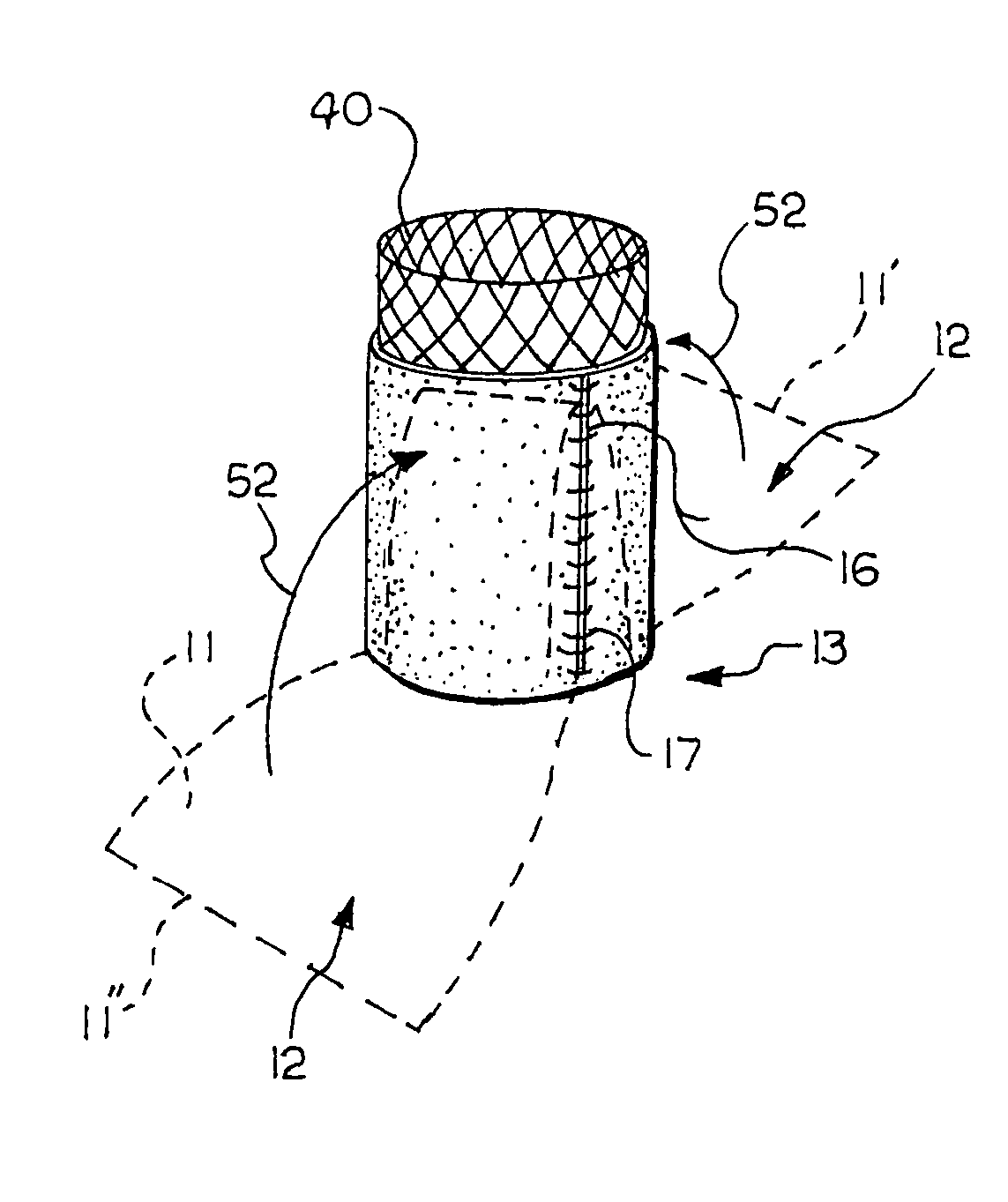
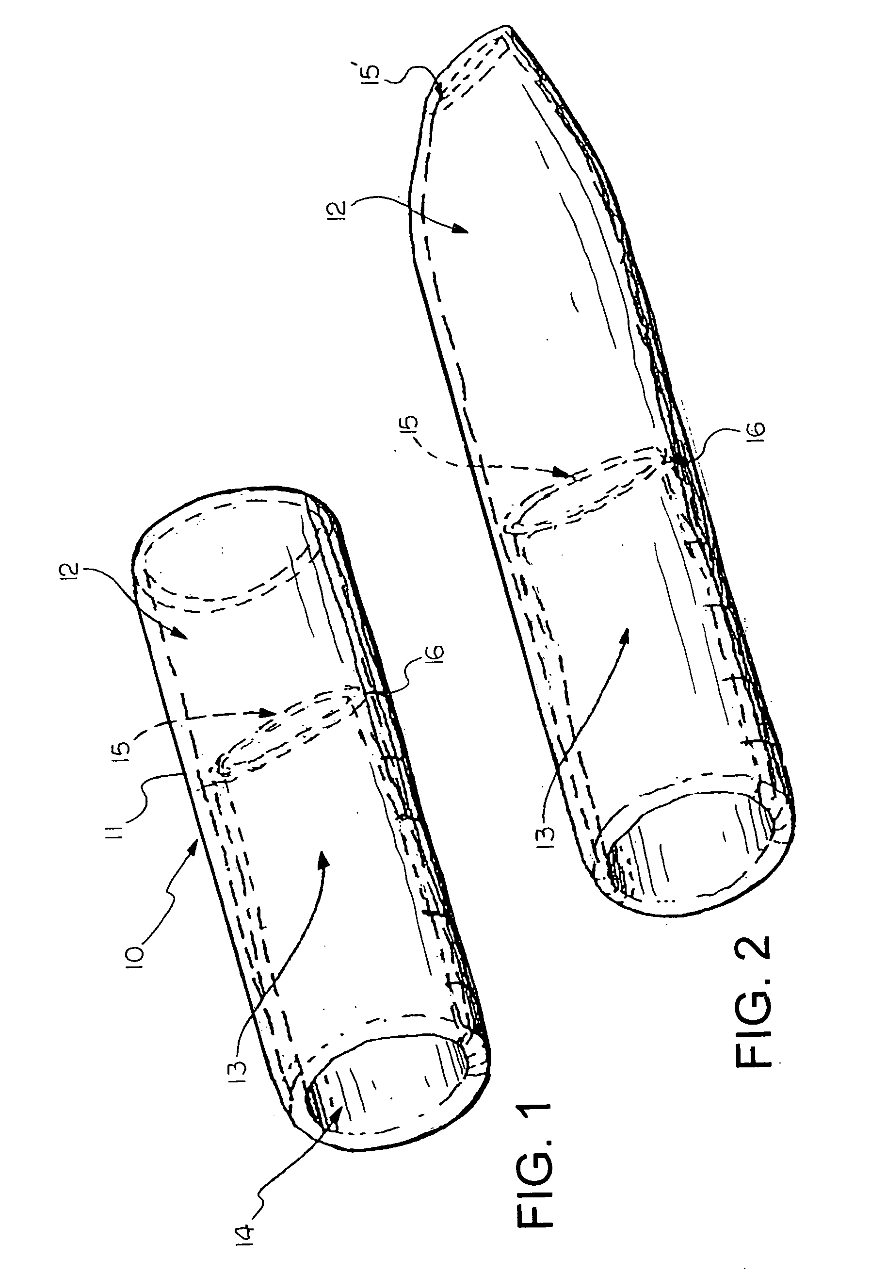
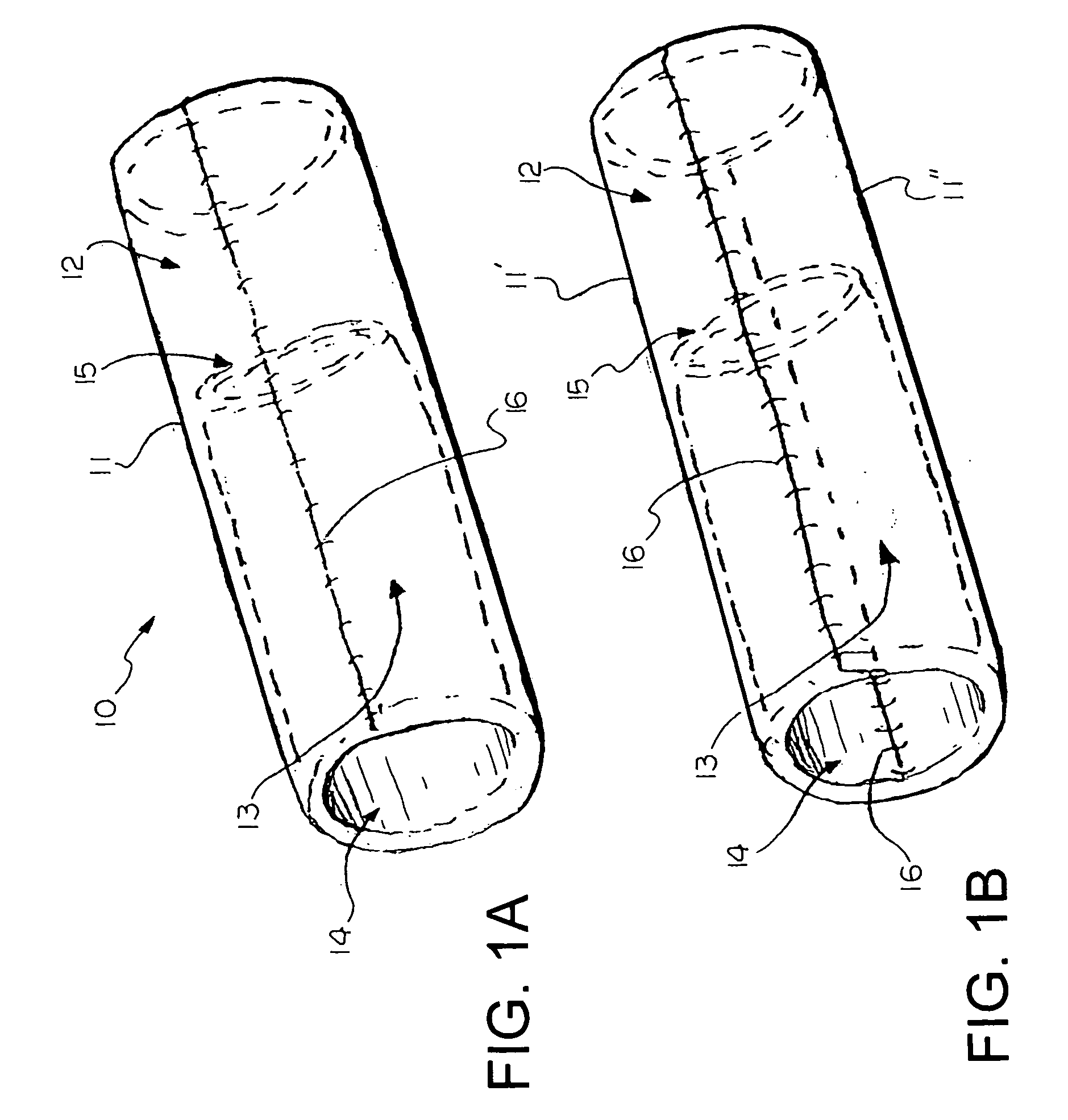
[0009] A prosthetic valve device for implantation in a body vessel is provided. In one embodiment, the device comprises a main body with first and second ends and defines a lumen. The second end is inverted into the lumen. A valve is disposed at the second end and is adapted to permit fluid flow through the lumen in a first direction and substantially prevent fluid flow through the lumen in a second, opposite direction.
[0010] In another embodiment, a prosthetic valve device according to the invention comprises a main body with first and second ends and defines a lumen. The second end is inverted into the lumen. A first valve is disposed at the first end and a second valve is disposed at the second end. The first and second valves are individually adapted to permit fluid flow through the lumen in a first direction and substantially prevent fluid flow through the lumen in a second, opposite direction.

Problems solved by technology

While natural valves may function for an extended time, some may lose effectiveness, which can lead to physical manifestations and pathology.
For example, venous valves are susceptible to becoming insufficient due to one or more of a variety of factors.
Over time, the vessel wall may stretch, affecting the ability of valve leaflets to close.
Furthermore, the leaflets may become damaged, such as by formation of thrombus and scar tissue, which may also affect the ability of the valve leaflets to close.
Once valves are damaged, venous valve insufficiency may be present and can lead to discomfort and possibly ulcers in the legs and ankles.

Method used


Image

  • Prosthetic valve devices and methods of making such devices
  • Prosthetic valve devices and methods of making such devices
  • Prosthetic valve devices and methods of making such devices

Examples


Embodiment Construction

[0044] The present invention relates to medical devices, and in particular to prosthetic valve devices and methods of making such devices. For the purposes of promoting an understanding of the principles of the invention, the following provides a detailed description of embodiments of the invention as illustrated by the drawings as well as the language used herein to describe the aspects of the invention. The description is not intended to limit the invention in any manner, but rather serves to enable those skilled in the art to make and use the invention. As used herein the terms comprise(s), include(s), having, has, contain(s) and the variants thereof are intended to be open ended transitional phrases, terms, or words that do not preclude the possibility of additional steps or structure.

[0045] As illustrated in FIG. 1, a prosthetic valve device of an embodiment of the present invention comprises a main body 11 having first and second ends 12, 13 and defining a lumen 14, the secon...


PUM


Abstract

Prosthetic valve devices for implantation in body vessels, and methods of making same, are provided. The device has a main body with first and second ends and defining a lumen, with the second end being inverted into the lumen. A valve is disposed at the second end. In multiple valve devices, valves are disposed at the first and second ends, and individually may be inverted into the lumen. The prosthetic valve devices may further include a support structure such as a stent. Methods of making a prosthetic valve device include providing a main body having first and second ends and defining a lumen, forming a valve at the second end, and inverting the second end into the lumen. Methods may further comprise forming multiple valves and may also include attaching a support structure.

Description

RELATED APPLICATIONS [0001] The present patent document claims the benefit of the filing date under 35 U.S.C. §119(e) of Provisional U.S. Patent Application Ser. No. 60 / 491,595, filed Jul. 31, 2003, which is hereby incorporated by reference in its entirety.FIELD OF THE INVENTION [0002] The present invention relates to medical devices, and in particular to prosthetic valve devices and methods of making such devices. BACKGROUND OF THE INVENTION [0003] By use of a closed circulatory system, animal bodies use many internal organs and vessels to transport fluids from one bodily location to another. Components of the circulatory system include the heart, blood vessels, and blood. The heart has valves (semilunar valves and atrioventricular valves) that regulate the flow of blood in the atria and the ventricles. Three examples of blood vessels are arteries, veins, and capillaries. Whereas arteries transport blood to organs throughout the body (i.e., away from the heart), veins carry blood b...

Claims


Application Information

Patent Timeline
IPC IPC(8): A61F2/06A61F2/24A61F2/90
CPCA61F2/2412A61F2/2415A61F2220/0075A61F2/2475A61F2/2418
Inventor CASE, BRIAN C.FLAGLE, JACOB A.
Owner COOK MEDICAL TECH LLC
Learn More