
Color chart

Inactive Publication Date: 2005-02-03
HOYA CORP
View PDF7 Cites 8 Cited by
  • Summary
  • Abstract
  • Description
  • Claims
  • Application Information

AI Technical Summary

Benefits of technology

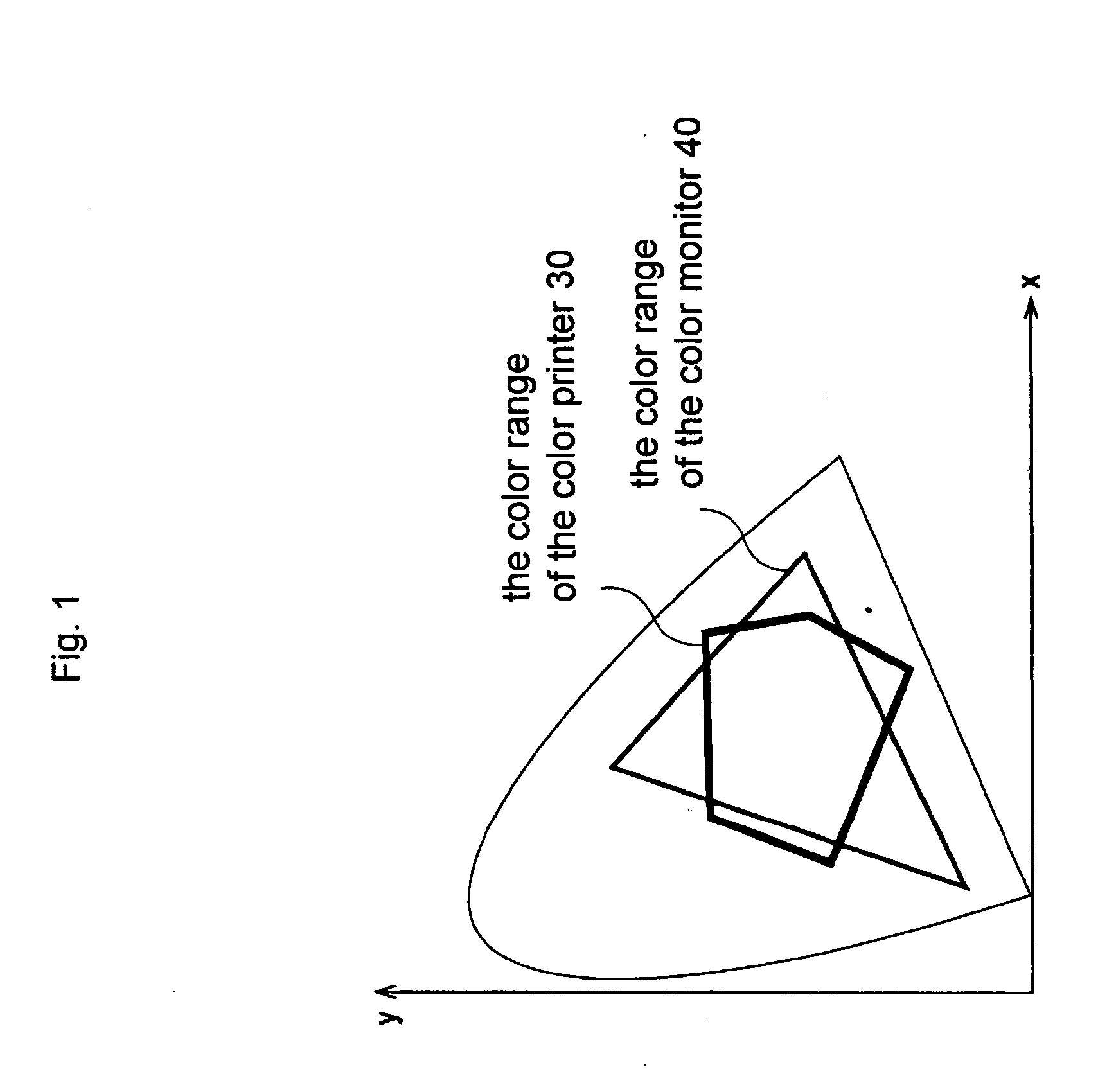
[0017] Therefore, an object of the present invention is to provide a device that can carry out the color adjustment of the color printer and the color monitor easily and objectively, where the connections are analogue signal connections.

Problems solved by technology

However, the above disclosed method does not disclose a method for the color adjustment of the color printer and the color monitor which are output devices.

Method used


Image

  • Color chart
  • Color chart
  • Color chart

Examples


first embodiment

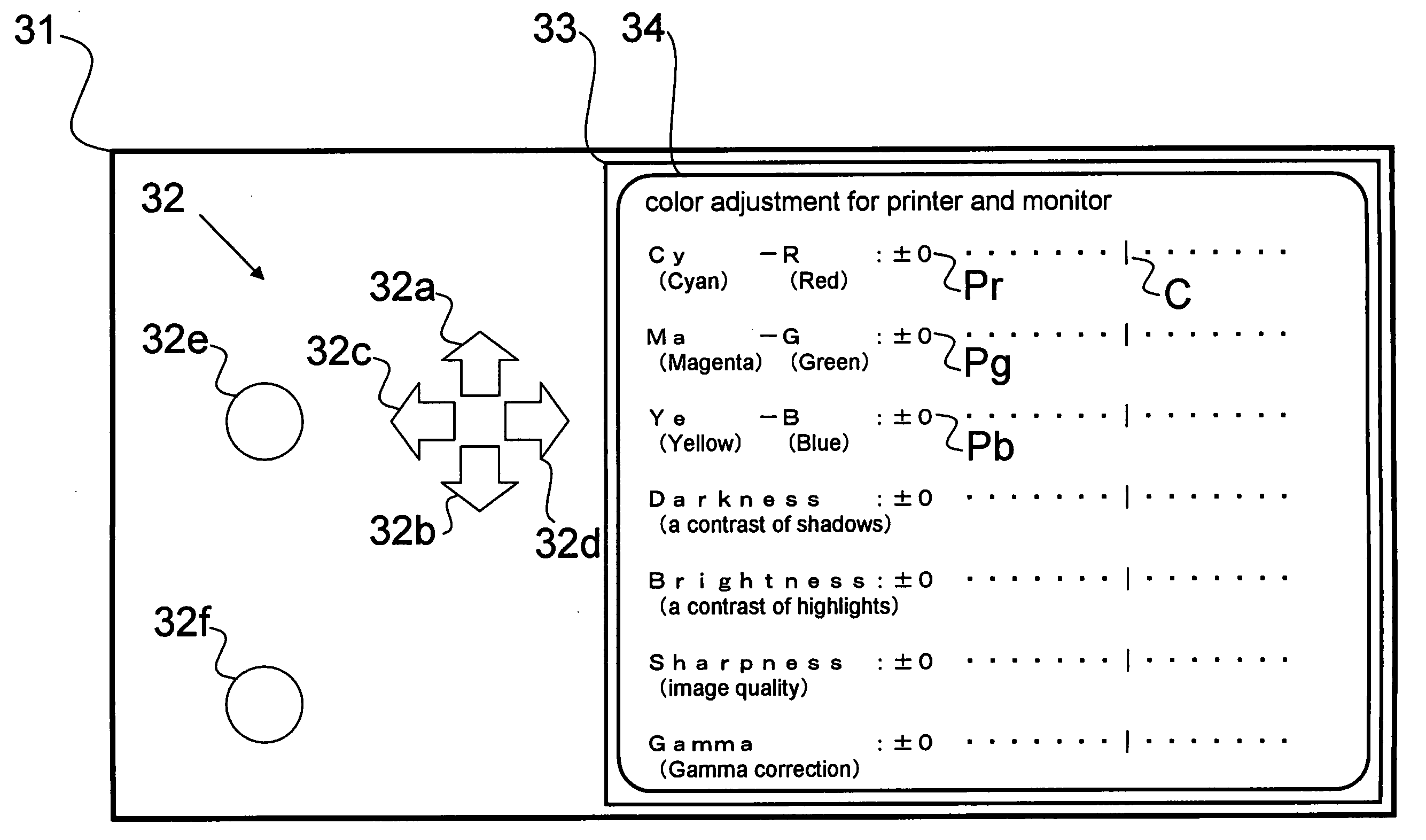
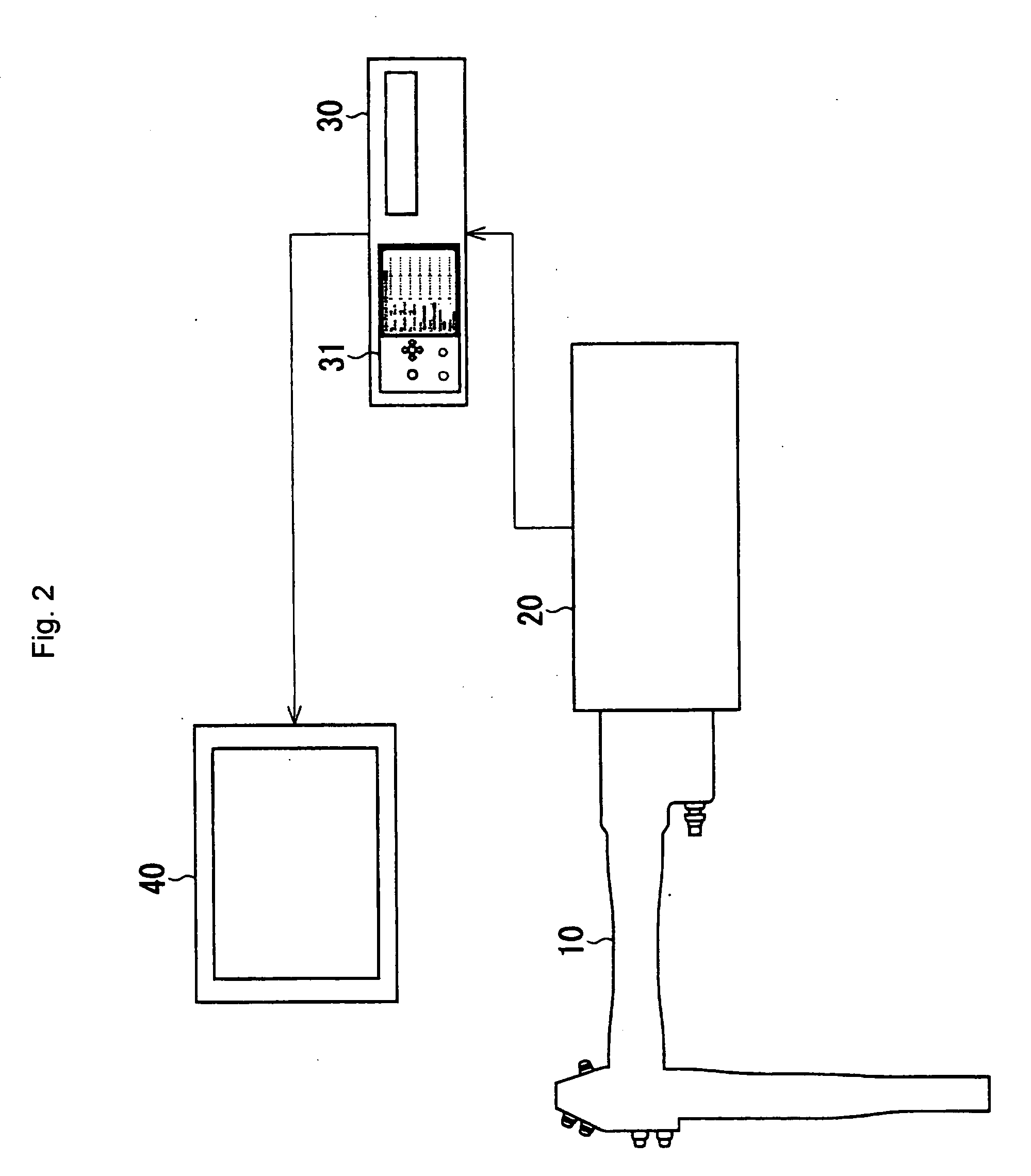
[0034] The present invention is described below with reference to the embodiments shown in the drawings. As shown in FIG. 2, an endoscope relating to a first embodiment is provided with a color scope 10, a color processing unit 20, a color printer 30, and a color monitor 40. The color scope 10 images a subject and is controlled by the color processing unit 20. The electric signals obtained during the imaging process are converted to image signals by the processing unit 20 and are then output to the color printer 30 and the color monitor 40. The converted image signals are analogue signals and are supplied to the color printer 30 and the color monitor 40. The supplied image signals can be converted to a hard copy, in other words printed out by the color printer 30, and kept as a soft copy, in other words stored in a memory and indicated on a color monitor 40. An operator can observe the photographic subject that was imaged with the color scope 10 as a first output image by the color ...

second embodiment

[0083] Next, the third and fourth color charts 51′ and 52′ are explained in the The third color chart 51′ has a first guide indication section 53. The fourth color chart 52′ has a second guide indication section 54. The first and second guide indication sections 53 and 54 show color-adjustment items and directions of a hue change, so that they can facilitate speeding up the color adjustment work.

[0084] The first guide indication section 53 on the third color chart 51′ is explained (see FIG. 9). The third color chart 51′ has the first guide indication section 53, which is outside the grid. The first guide indication section 53 consists of first, second, and third adjusting guides 53a, 53b, and 53c. The color gradient inside the grid of the third color chart 51′ is similar to the color gradient inside the grid of the first color chart 51.

[0085] The first adjusting guide 53a has a cyan guide cell B1, a red guide cell B2, and a first line segment L1 which has right and left direction ...


PUM


Abstract

A color chart for a color adjustment of a color printer and a color monitor attached to an endoscope, has a predetermined number of color cells. The color cells have the same form, and are arranged in one of a grid state and a linear state. Each of the color cells is formed by blending two colors from a group of three colors comprising red, green, and blue, according to a predetermined ratio, in an additive color process. The color cells show a gradation of color such that a color tone of each of the color cells changes continuously in one direction.

Description

BACKGROUND OF THE INVENTION [0001] 1. Field of the Invention [0002] The present invention relates to an endoscope and in particular to an apparatus for the color adjustment of a color printer and a color monitor connected to the endoscope. [0003] 2. Description of the Related Art [0004] Endoscopes are used widely in the field of medicine, especially for the observation and the inspection of the inside of an organ. Such endoscopes consist of a color scope, a color processing unit, a color printer, and a color monitor. The color scope images a subject and is controlled by the color processing unit. The electric signals obtained during the imaging process are converted to image signals by the processing unit and are then output to the color printer and the color monitor. The converted image signals are analogue signals and are supplied to the color printer and the color monitor. The supplied image signals can be converted to a hard copy, in other words printed out by the color printer,...

Claims


Application Information

Patent Timeline
IPC IPC(8): H04N1/50H04N1/58H04N1/60
CPCH04N1/6055
Inventor OTA, NORIKOITO, SHUNICHIABE, NOBUAKI
Owner HOYA CORP
Learn More