
Collapsible basket assembly

a basket and assembly technology, applied in the field of basket assembly, can solve the problems of reducing the volumetric space, affecting the manner and sturdiness of the basket construction, and reducing the cost of transportation of the basket from the manufacturer to the retailer, so as to reduce the volumetric space

Inactive Publication Date: 2005-02-03
LUCK STONE CORP
View PDF4 Cites 2 Cited by
  • Summary
  • Abstract
  • Description
  • Claims
  • Application Information

AI Technical Summary

Benefits of technology

[0011] A further object of the present invention is to provide for a novel collapsible basket for the collection and transport of tennis balls which basket exhibits a sturdiness and longevity.
[0012] A still further object of the present invention is to provide for a novel collapsible basket for the collection and transport of tennis balls which collapsible basket reduces the volumetric space required in shipping and storing the collapsible basket. SUMMARY OF THE INVENTION

Problems solved by technology

Its one drawback had not thing to do with its intended purpose, rather the drawback had to do with the manner and sturdiness of its construction.
As such the cost of transportation of the baskets from the manufacturer to the retailer was costly because of the space requirement per basket.
A further expense was realized by the retailer in that the basket took up significant storage space in inventory.
It is this area of the basket which takes the most stress when collecting the spent tennis balls because the basket is literally jammed over the tennis balls repeatedly in picking them up.
As such it comes into abrupt and significant contact with the court surface repeatedly such that the sturdiness and longevity of the prior art baskets is not achieved by the collapsible basket of Yeh at the expense of lowering shipping and inventory costs.

Method used


Image

  • Collapsible basket assembly
  • Collapsible basket assembly
  • Collapsible basket assembly

Examples


Embodiment Construction

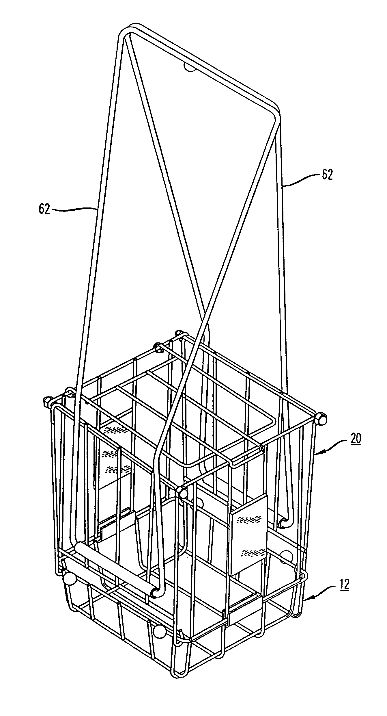
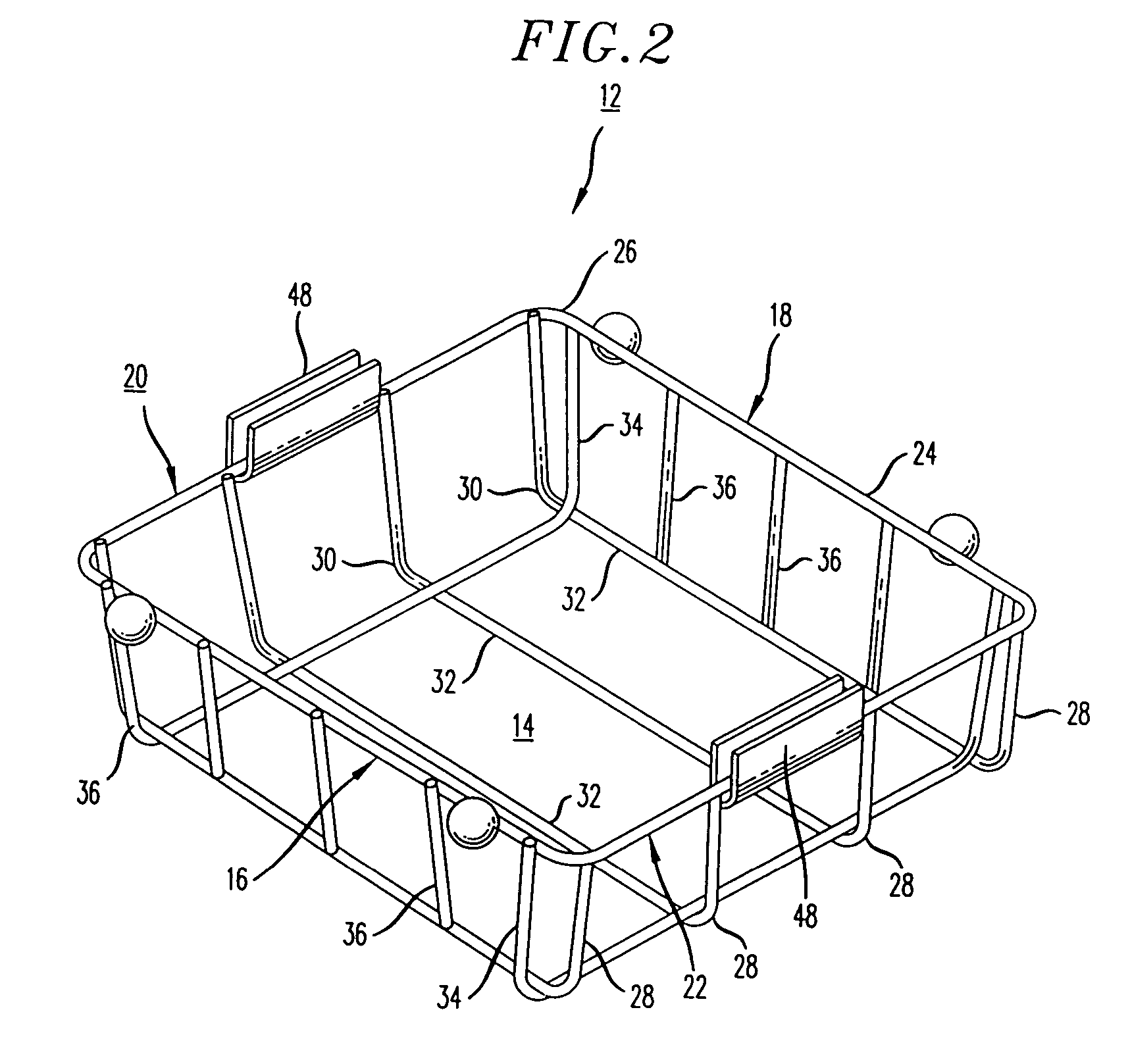
[0020]FIG. 1 is a perspective view of the collapsible basket assembly of the present invention which comprises a basket member 20 and a pair of U-shaped members 62 which serve as handles and / or support legs. The basket 20 is formed of a tray member 12 which has an integral bottom wall 14 formed integrally with a front wall 16, rear wall 18, and side walls 20 and 22. Each of the walls and bottom is formed of a plurality of metal rods welded to one another or otherwise suitable secured so as to form tray member 12 with an upper peripheral edge 24.

[0021] Each of the walls 16, 18, 20, and 22 and bottom wall 14 is in the form of a grate. In a preferred embodiment, tray member 12 is formed of an upper continuous rod 26 formed in the shape of a square defining the upper peripheral edge of tray 12. Side walls 20 and 22 and bottom wall 14 are formed by four spaced apart identical rods 28, each having a 90 degree bend 30 at opposing ends such that when the ends are secured to opposing upper ...


PUM


Abstract

A collapsible basket assembly for collecting and transporting tennis balls the basket assembly having a tray member defining a bottom wall of the basket the tray member further comprising upstanding partial side walls integral with the bottom wall each partial upstanding side wall terminating with an upper edge, two extension side walls rotatably mounted to opposing upper edges of partial upstanding side wall portions of the tray, and two extension side walls snap fit to opposing edges of two remaining opposed partial upstanding side walls of the tray member, snap fit extension side members having a hoop formed at opposing ends of their top edge for engagement with protrusions extending from opposing ends of the upper edges of the rotatable extension side members, the side members being secured by a fastening means on the protrusions, a bracket member horizontally secured to the outer surface of each rotatable extension side members for the removable receipt of a U-shaped member serving as a leg support or handle for the collapsible basket, the leg supports being held in either a vertical upward position or vertical downward position by a pair of fixed spheres secured to the top edge of opposing partial side walls of the tray to which the rotatable extension sides are secured.

Description

BACKGROUND OF THE INVENTION [0001] 1. Field of the Invention [0002] The present invention relates to a basket assembly, and more particularly to a collapsible basket assembly for the collection and transport of tennis balls. [0003] 2. Description of the Prior Art [0004] When an individual is practicing tennis or learning the game of tennis, the individual normally practices a variety of shots on a repetitive basis. This prompts the need for a supply of tennis balls easily available to the individual for practice. At the conclusion of practice there is a need to collect the spent tennis balls for reuse by another individual or for reuse at a later time. [0005] A tennis basket assembly was therefore developed which was fabricated of metal or steel rods bent, formed and / or welded to form a cage or basket having a bottom wall integral with four upstanding side walls and a pivotally mounted top wall for operation as a closure means. The space between the steel or metal rods forming the i...

Claims


Application Information

Patent Timeline
Patent Type & Authority Applications(United States)
IPC IPC(8): A63B47/02
CPCA63B47/02A63B2243/0083A63B2210/50A63B2102/02
Inventor HELLERSON, ROBERT
Owner LUCK STONE CORP
Learn More