
Storage subsystem and information processing system

Inactive Publication Date: 2005-01-27
HEWLETT PACKARD DEV CO LP
View PDF6 Cites 9 Cited by
  • Summary
  • Abstract
  • Description
  • Claims
  • Application Information

AI Technical Summary

Benefits of technology

[0008] An object of the present invention is to provide the storage subsystem equipped with the communicating means of loop topology, for preventing the decrease in the performance and / or reliability to the minimum, even if any failure occurs on the storage subsystem.
[0009] Another object of the present invention is to provide the storage subsystem equipped with the communicating means of loop topology, for determining the failing part and for recovering from the failure quickly, simply and precisely.
[0010] Another object of the present invention is to provide the storage subsystem equipped with multiple communicating means of loop topology, for recovering reliably from the multiple failure having influence upon the multiple loops of communicating means.
[0011] An object of the present invention is to provide the information processing system equipped with the communicating means of loop topology, for minimizing the decrease in the performance and / or reliability, even if any failure occurs in the information processing system.
[0012] Another object of the present invention is to provide the information processing system equipped with the communicating means of loop topology, for determining the failing part and for recovering from the failure in the processing system quickly, simply and precisely.
[0019] By controlling these PBCs, the location of failing part in the loop can be determined. In specific embodiments, the location of the failing part can be determined by repeating operation to confirm the availability of the communication for the effective portion of the loop varying effective portion of the loop by controlling the PBC. If any operable portion of the loop is detected, the detected operable portion within the loop continues to be used, and only the inoperable portion of the loop is switched to the another loop; thereby, the decrease in the performance can be prevented to the minimum.

Problems solved by technology

For example, according to conventional FC Loop technology, once the fibre channel loop is broken at any point, it becomes substantially impossible to communicate between a controller and each drive connected to the fibre channel loop.

Method used


Image

  • Storage subsystem and information processing system
  • Storage subsystem and information processing system
  • Storage subsystem and information processing system

Examples


Embodiment Construction

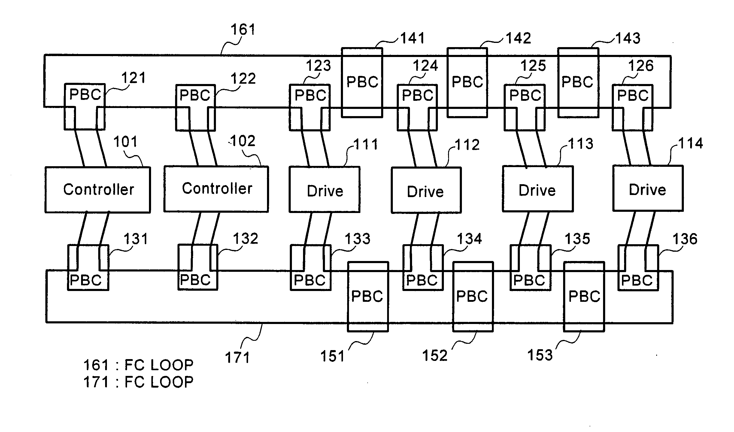
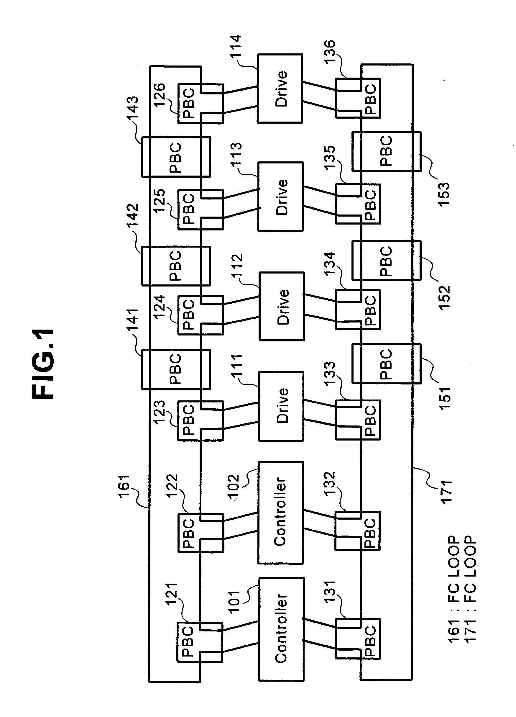
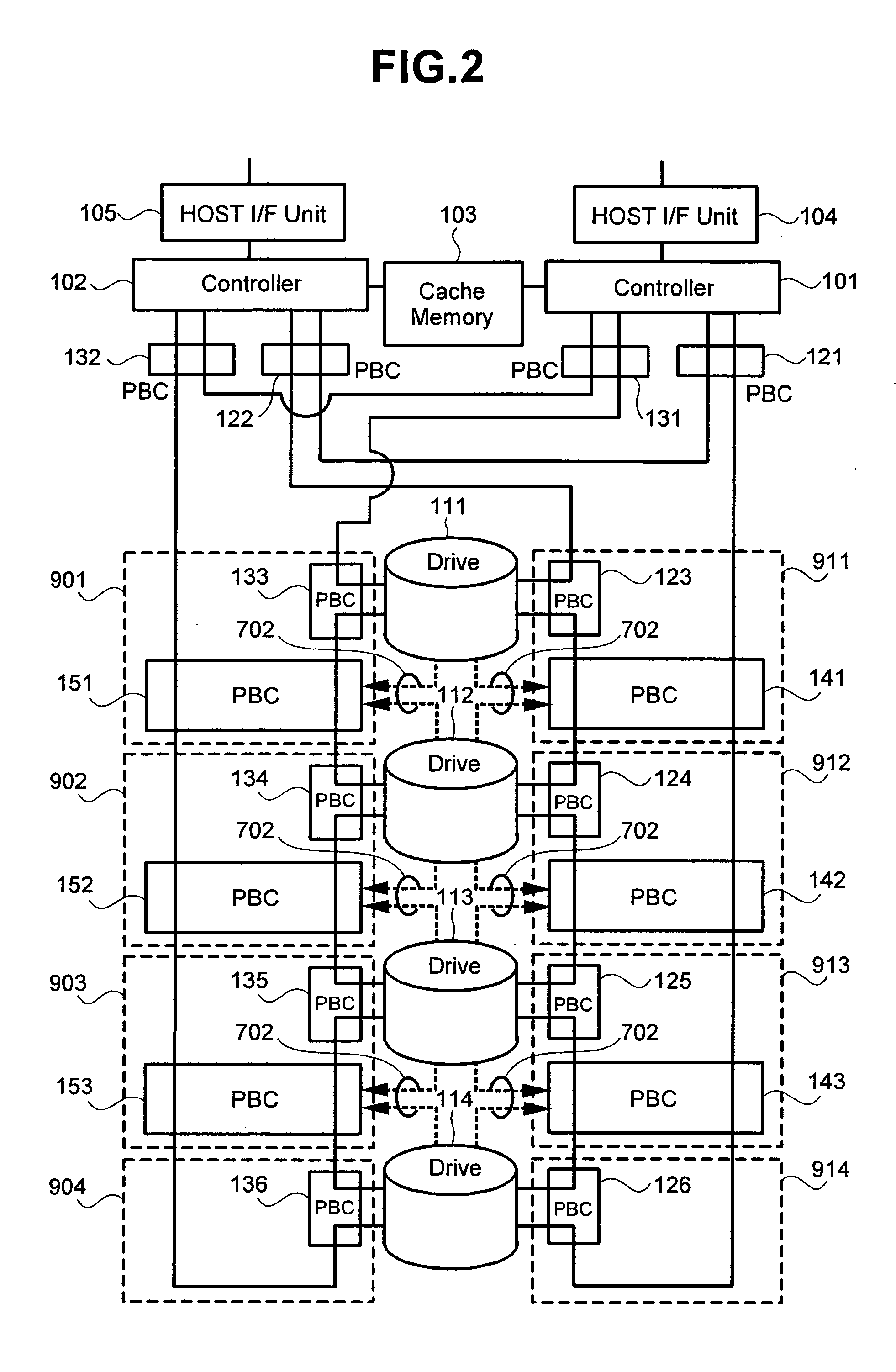
[0032] The present invention provides techniques for improved control and communication between controllers and drive units connected by a fibre channel loop. Specific embodiments can provide storage subsystems, methods and apparatus for use in information processing environments, for example. Embodiments can determine when each drive is disconnected from the loop in the external storage subsystem structured by using the FC Loop, and thereupon, the FC Loop can be controlled by bridging the communication path using the PBC so that the loop is not broken.

[0033] In one storage subsystem configuration technique, not only in the case of failure, but also in the normal operation, it is possible to control the PBC in order to connect the rarely used drive to the loop only when the drive is actually accessed or to balance the use ratio of each loop, for example. For a more detailed description of one such technique, reference may be had to a Japanese unexamined published patent application...


PUM


Abstract

According to the invention, techniques for detecting and recovering from errors occurring in disk drive subsystems having a controller and drive units connected by a fibre channel loop. Specific embodiments can provide storage subsystems, methods and apparatus for use in information processing environments, for example. Embodiments can determine when each drive is disconnected from the loop in the external storage subsystem structured by using the FC Loop, and thereupon, the FC Loop can be controlled by bridging the communication path using the PBC so that the loop is not broken.

Description

CROSS-REFERENCES TO RELATED APPLICATIONS [0001] This application claims priority from Japanese Patent Application Reference No. P00-032873, filed Feb. 10, 2000. BACKGROUND OF THE INVENTION [0002] The present invention relates to techniques for use in a storage subsystem and an information processing system, and in particular to techniques for detecting and recovering from errors occurring in storage subsystems having two or more components linked together by a communication link with a loop topology such as the fibre channel loop. [0003] Conventional high capacity storage subsystems can be comprised of two or more hard disk drives which are connected by a Fibre Channel (FC). In the connecting topology of the FC Loop (FIBRE CHANNEL ARBITRATED LOOP (FC-AL)), each drive and a controller which controls the drive in the storage subsystem are connected with one another by a loop topology. A port bypass circuit (PBC) is installed in a connecting part between each drive and the FC Loop in o...

Claims


Application Information

Patent Timeline
IPC IPC(8): G06F3/06G06F13/10G06F11/00G06F11/07G06F11/14G06F11/20G06F12/16G06F13/00G11B19/02
CPCG06F11/0727G06F11/079G06F11/2092G06F11/201G06F11/0793
Inventor NAGATA, KOJITAKAMOTO, KENICHI
Owner HEWLETT PACKARD DEV CO LP
Learn More