
Method and device for controlling the speed of a vehicle

a technology for controlling the speed of a vehicle and a method, applied in the direction of adaptive control, electric control, instruments, etc., can solve the problems of reducing comfort and the complexity of the application of the approach, and achieve the effect of reducing the complexity of the application

Inactive Publication Date: 2005-01-27
ROBERT BOSCH GMBH
View PDF21 Cites 6 Cited by
  • Summary
  • Abstract
  • Description
  • Claims
  • Application Information

AI Technical Summary

Benefits of technology

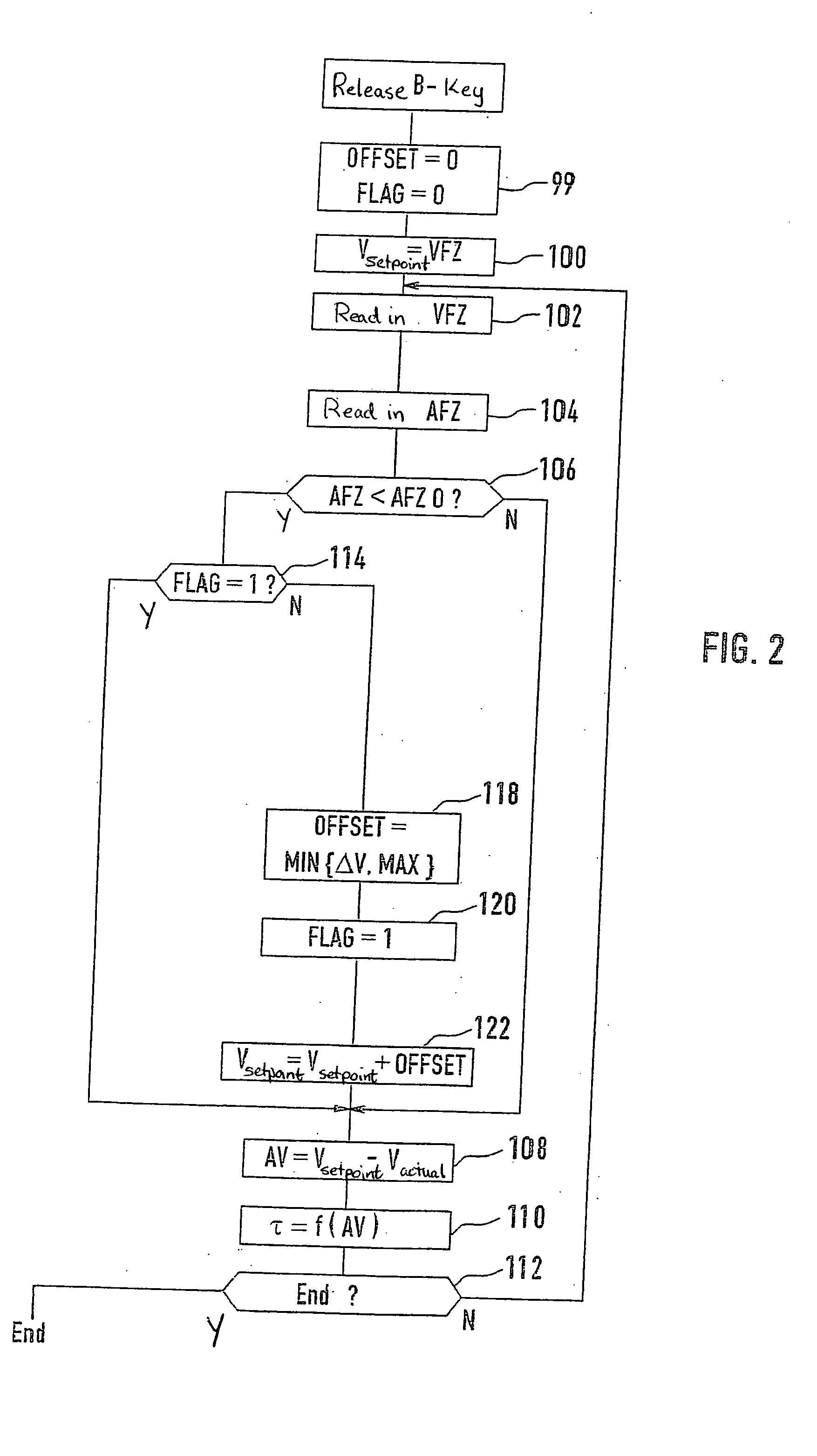
[0005] In accordance with the present invention, by changing the driving speed setpoint value for the transition from an acceleration or deceleration process to constant speed as a function of the existing system deviation, a comfortable transition may be provided without severe changes in torque or fluctuations in the vehicle speed.
[0006] Thus, the control quality of the controller may be improved over the entire range of use, since in the transition from a dynamic phase to a stationary phase the tendency for the vehicle speed to fluctuate may be greatly reduced.
[0007] Furthermore, the correction of the setpoint value as a function of the existing system deviation is easy to apply and does not require complex data collection for characteristic curves. The application time and thus also the application costs may be significantly reduced as a result.

Problems solved by technology

The jump-like response of the actuating signal results, at least in many cases, in reduced comfort.
Furthermore, this approach has disadvantages in its application complexity.

Method used


Image

  • Method and device for controlling the speed of a vehicle
  • Method and device for controlling the speed of a vehicle
  • Method and device for controlling the speed of a vehicle

Examples


Embodiment Construction

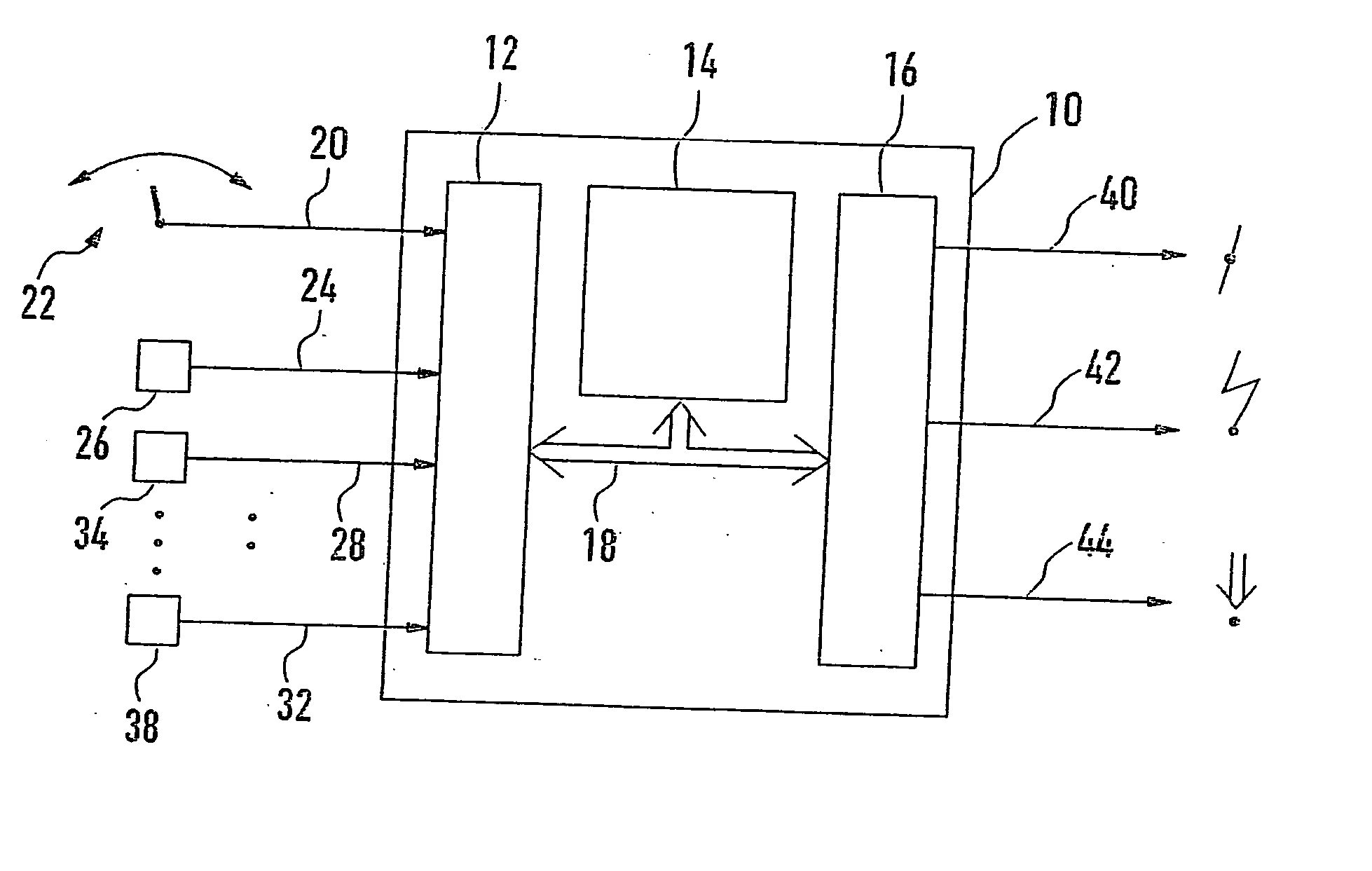
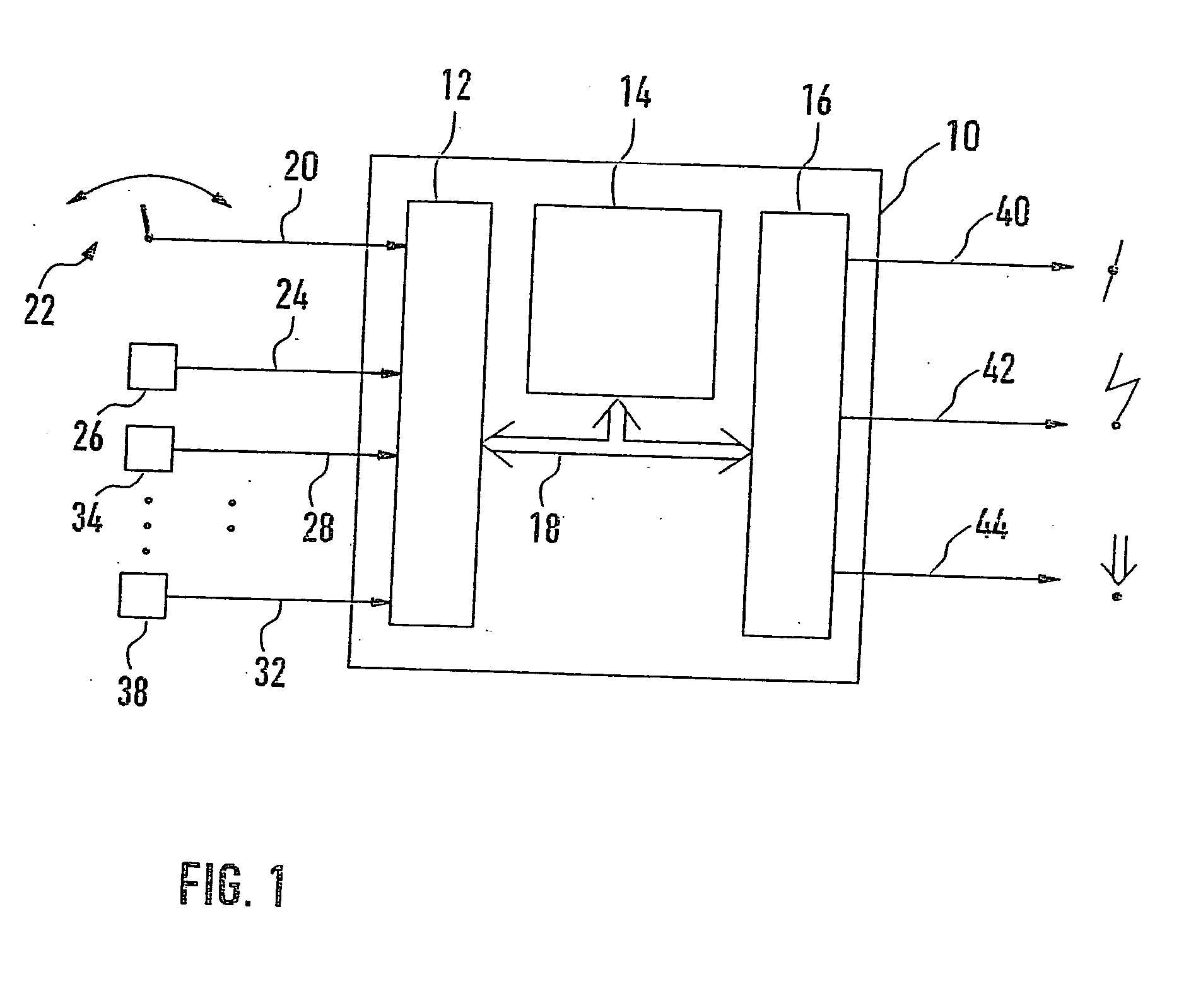
[0013]FIG. 1 illustrates a control unit 10 composed essentially of an input circuit 12, microcomputer 14, and output circuit 16. These elements are connected to one another for data exchange via a communications system 18. According to an example embodiment, control unit 10 represents a control unit which controls the drive power of a drive motor of a vehicle. In many applications a vehicle speed controller is also included within the scope of such a control unit. The following description focuses on the portion of control unit 10 which is directly connected to the vehicle speed controller, whereas the other functions which are a part of control unit 10 are not described in detail.

[0014] Input circuit 12 of control unit 10 is supplied with a first input line 20 which connects control unit 10 to an operator control 22, actuatable by the driver, with which the driver may specify the functional mode of the vehicle speed controller or set the setpoint speed. An input line 24 is also pr...


PUM


Abstract

A method and a device for controlling the speed of a vehicle are described. In the transition from a dynamic to a steady-state operating state, the initially accepted setpoint value is corrected using a correcting value which depends on the system deviation prevailing at the time when the longitudinal acceleration of the vehicle has reached, exceeded, or fallen below a predetermined threshold value.

Description

FIELD OF THE INVENTION [0001] The present invention relates to a method and a device for controlling the speed of a vehicle. BACKGROUND INFORMATION [0002] A vehicle speed controller is known from German Published Patent Document No. 28 42 023 (U.S. Pat. No. 4,337,511), in which the driving speed of the vehicle is adjusted as a function of a driving speed setpoint value predetermined by the driver. The output signal of the vehicle speed controller acts on a power controller for the vehicle engine. Depending on the design, the vehicle speed controller itself exhibits proportional, integral, and / or differential response. To improve the dynamic response of the controller in a control process which causes a change in driving speed, such as an actuation of the acceleration key, the setpoint value of the vehicle speed control is set to the value of the actual speed measured upon actuation of the key plus a fixed offset value, and change of the vehicle speed is implemented by ramp-shaped ch...

Claims


Application Information

Patent Timeline
IPC IPC(8): B60K31/00B60K31/04F02D29/02G05B13/02G05D1/02
CPCB60W2520/105B60K31/047
Inventor GUENTHNER, JENSSCHULTE, HANSKNOBLOCH, BORISKUSTOSCH, MARIOMUEHLBAUER, CHRISTIAN
Owner ROBERT BOSCH GMBH
Learn More