
Dynamic object avoidance with automated guided vehicle

Inactive Publication Date: 2005-01-27
DEMATIC
View PDF4 Cites 56 Cited by
  • Summary
  • Abstract
  • Description
  • Claims
  • Application Information

AI Technical Summary

Problems solved by technology

However, changes to the guide path still require operation of a computer both to change the guide path and to restore it to its initial condition.

Method used


Image

  • Dynamic object avoidance with automated guided vehicle
  • Dynamic object avoidance with automated guided vehicle
  • Dynamic object avoidance with automated guided vehicle

Examples


Embodiment Construction

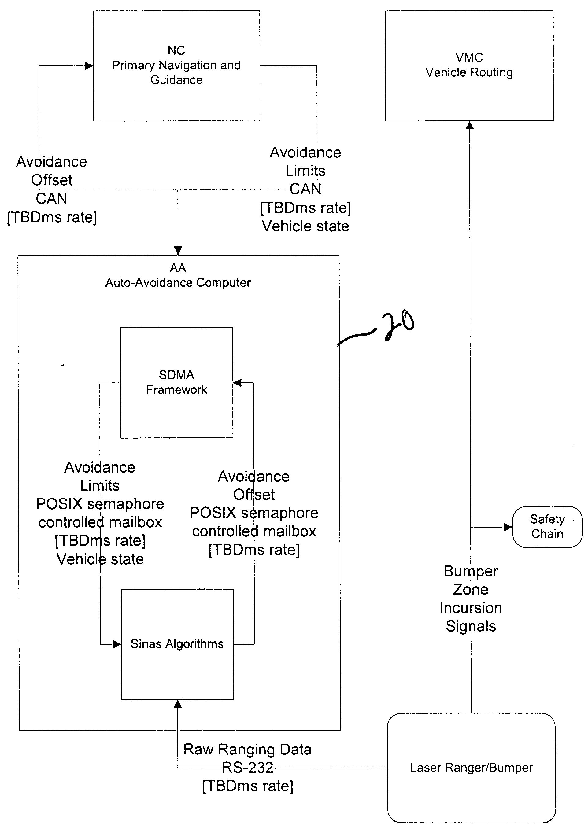
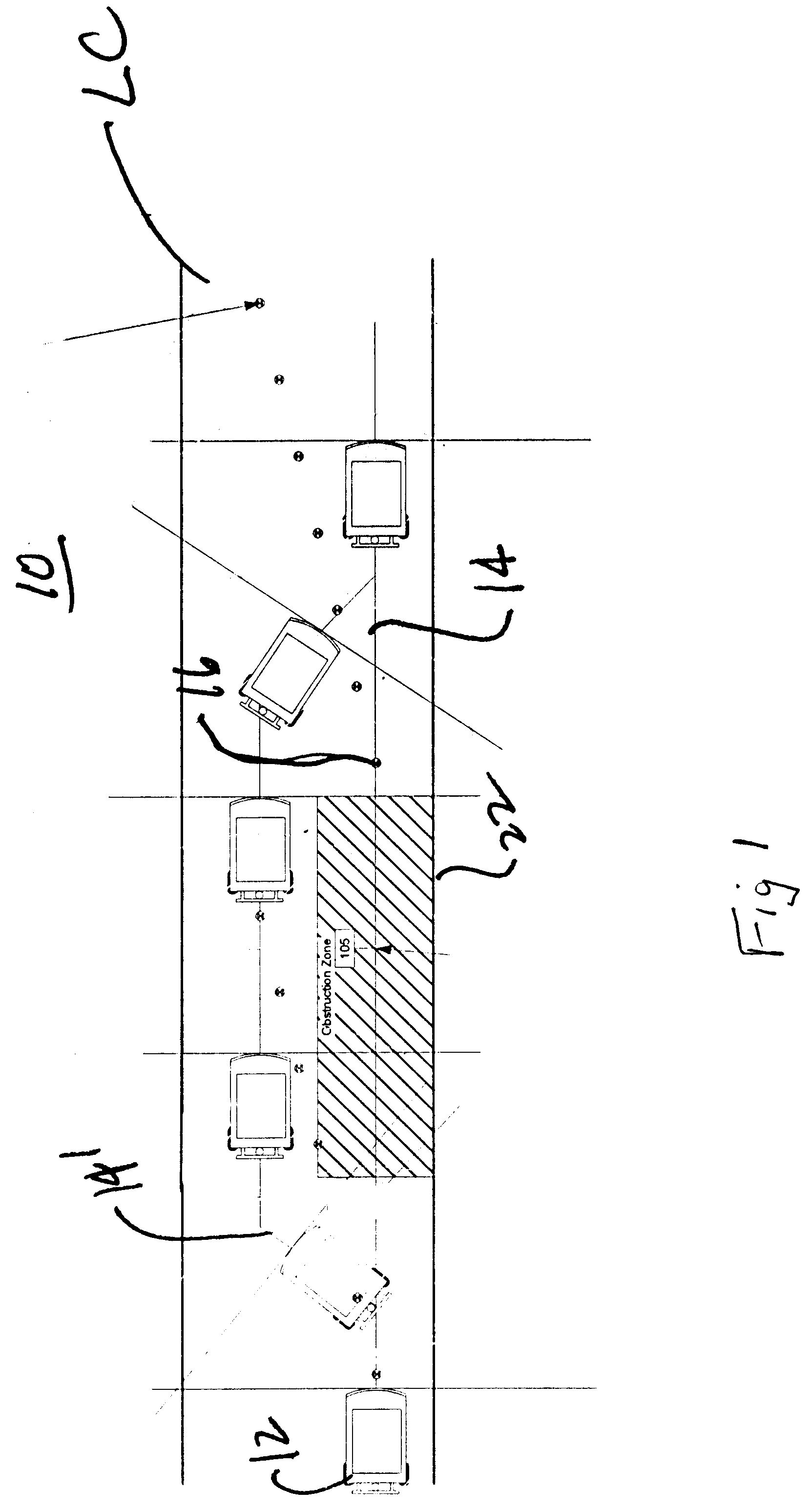
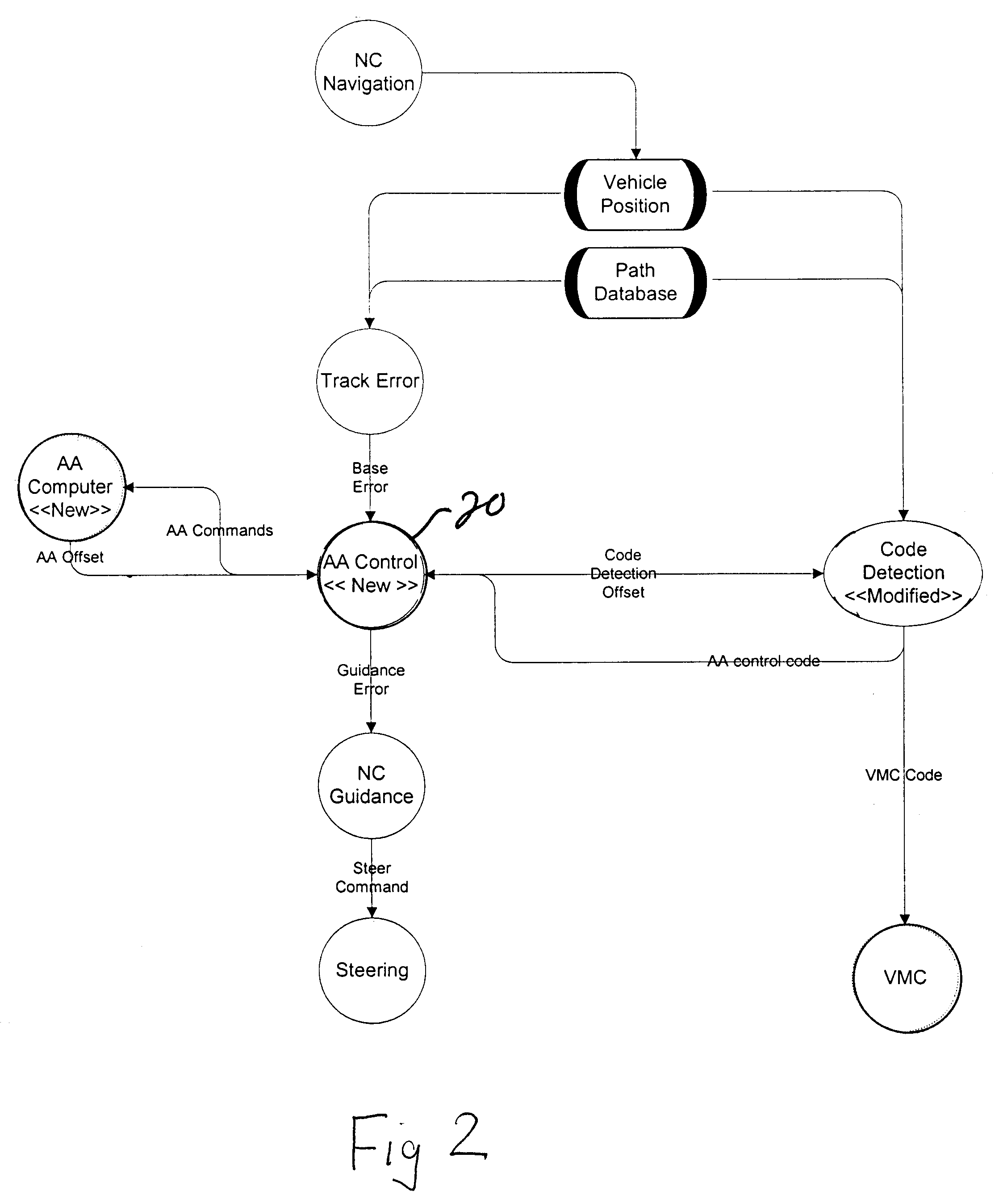
[0013] Referring now to the drawings and the illustrative embodiments depicted therein, an automated-guided vehicle system and method 10 includes one or more guided vehicles 12 which is controlled, at least in part, by a central dispatcher (not shown) which issues commands to the vehicle 12 as to its destination. In the illustrative embodiment, the vehicle autonomously travels along a guide path 14, which is a virtual guide path. The virtual guide path is defined in memory, such as in a computer on-board vehicle 12. It should be understood that the invention may be applied to other types of systems, such as systems in which a central control provides detailed steering instructions to vehicle 12. Vehicle 12 includes a navigation computer NC which provides dead-reckoning guidance to the vehicle. Such dead-reckoning systems are well known in the art and will not be described in more detail herein. Suffice it say, such dead-reckoning systems produce drift from the guide path. Therefore,...


PUM


Abstract

A method and apparatus for guiding an automated-guided vehicle includes providing a guide path defined with respect to a physical path and controlling a vehicle to generally follow the guide path. The presence of an obstacle at the guide path is detected, such as with a laser scanner, radar detector, or the like. The vehicle is controlled around the obstacle and back to the guide path. This may be accomplished by generating an offset to the guide path at the detected obstacle.

Description

CROSS REFERENCE To RELATED APPLICATIONS [0001] The present application claims the benefit of U.S. provisional application Ser. No. 60 / 481,113, filed Jul. 21, 2003, for DYNAMIC OBJECT AVOIDANCE WITH AUTOMATED GUIDED VEHICLE, which is hereby incorporated herein by reference in its entity.BACKGROUND OF INVENTION [0002] The present invention relates to an automated-guided vehicle (AGV) control and, in particular, to a method and apparatus for dynamically detecting objects in the path of travel of the vehicle and guiding the vehicle around the object, known as an “obstacle.”[0003] AGV systems are used extensively today in a wide variety of material handling applications. AGVs come in a wide variety of types from those carrying cargo on their back to those that tow trains of cargo behind them on carts, to still other types. In order for each AGV to be able to automatically guide itself throughout a factory or plant, it must be able to determine its position within the factory and the orie...

Claims


Application Information

Patent Timeline
IPC IPC(8): G05D1/02G06G7/78
CPCG05D1/024G05D1/0257G05D1/0274G05D1/027G05D1/0272G05D1/0261
Inventor ZEITLER, DAVID W.WERNER, MATTHEW L.KOFF, GARRY A.
Owner DEMATIC
Learn More