Puncturing tool for puncturing catheter shafts

a technology for puncturing tools and catheter shafts, which is applied in the direction of catheters, chairs, stools, etc., and can solve problems such as less tear resistan

Active Publication Date: 2005-01-27
WL GORE & ASSOC INC
View PDF94 Cites 20 Cited by
  • Summary
  • Abstract
  • Description
  • Claims
  • Application Information

AI Technical Summary

Benefits of technology

[0022] The ability to exit the back end of a guidewire through the wall of the catheter at any desired location along the length of the puncturable section of the catheter allows the catheter assembly to be used effectively as desired in either OTW or RX mode.

Problems solved by technology

These materials may also offer good translucency, but may be less tear resistant than the helically wrapped ePTFE thin coverings.

Method used


Image

  • Puncturing tool for puncturing catheter shafts
  • Puncturing tool for puncturing catheter shafts
  • Puncturing tool for puncturing catheter shafts

Examples


Embodiment Construction

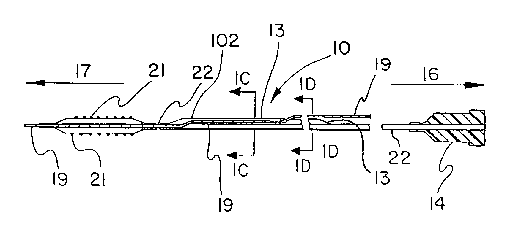
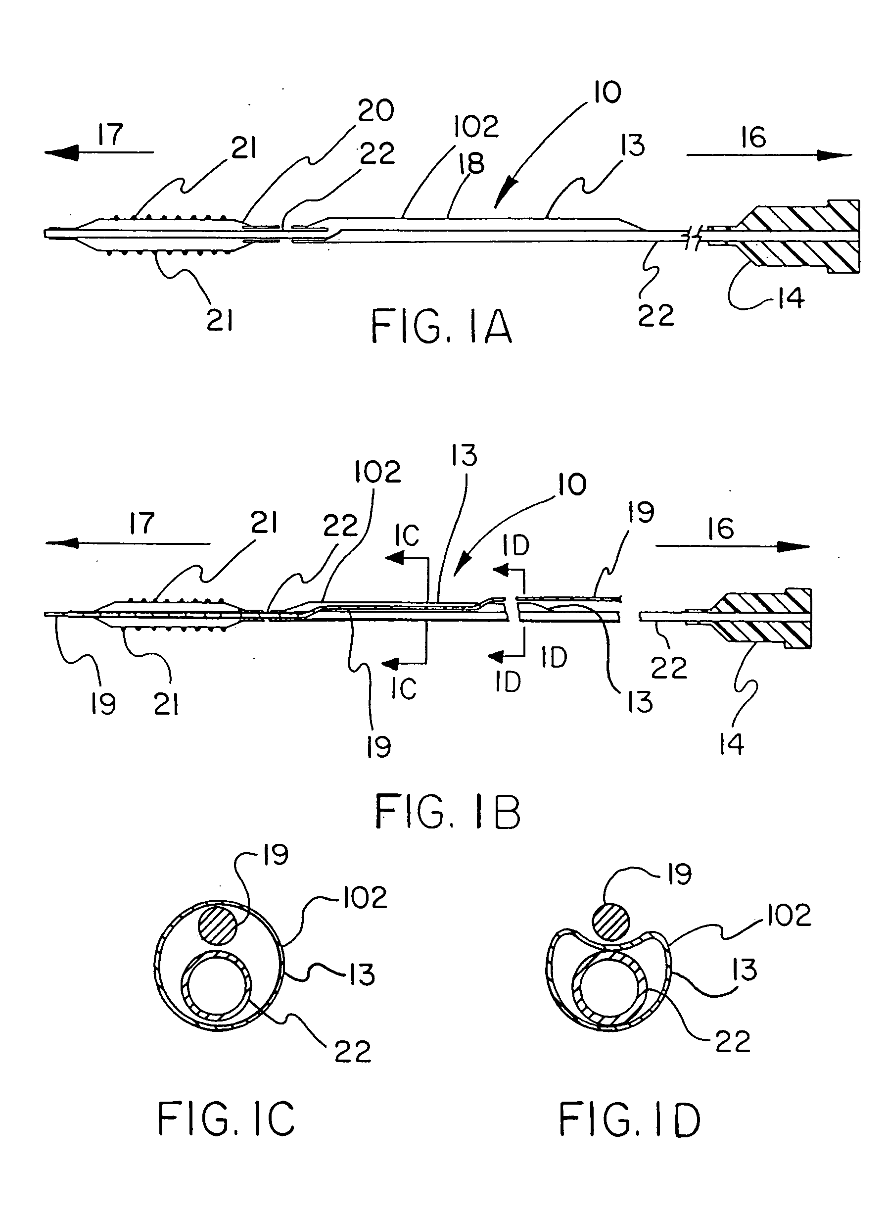
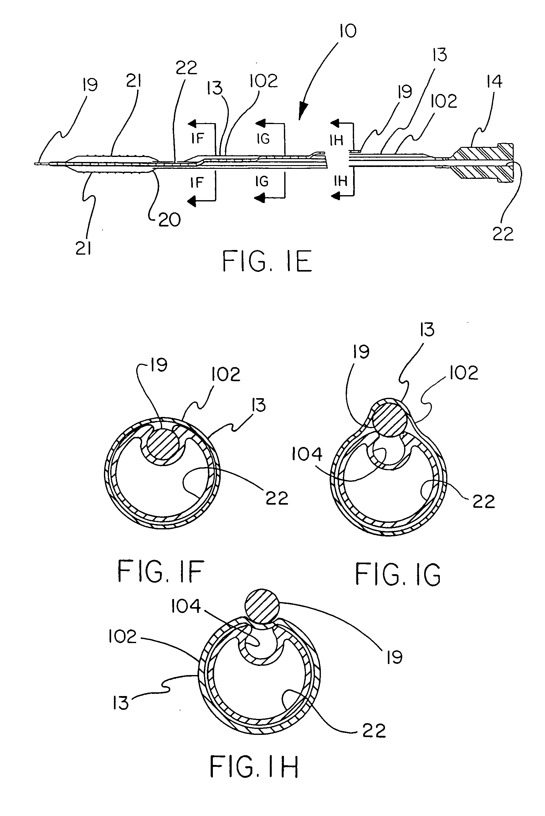
[0062]FIGS. 1A-1H describe the catheter 10 of the present invention provided with a thin, puncturable cover 102 over the guidewire lumen 18. Typically, catheter 10 may include devices such as a catheter balloon 20 and / or stent 21 at its distal end 17 and a hub 14 at the proximal end 16. As shown by FIGS. 1A-1H, the thin, puncturable cover 102, in this instance a thin-walled a thin tubular sheath 13 (forming guidewire lumen 18) designed to be punctured by the back end of a guidewire 19, may be placed coaxially about the inflation lumen 22. The length of the thin tubular sheath 13 may extend over all or part of the length of catheter shaft.

[0063] After feeding guidewire 19 through the distal section of the guidewire lumen 18 and into the thin-walled tubular sheath 13, the physician may chose any desired location along the length of thin-walled tubular sheath 13 at which to puncture the thin, puncturable cover 102 with the guidewire 19. In this fashion the physician may select his pre...


PUM


Abstract

Puncturing tools that cause an aperture to be pierced through the wall of a guidewire lumen of a catheter shaft at a location at which it is desired to have a guidewire exit the guidewire lumen.

Description

CROSS REFERENCE TO RELATED APPLICATIONS [0001] This application is a continuation-in-part of application Ser. No. 10 / 402,803, filed Mar. 28, 2003, which is a continuation-in-part of application Ser. No. 10 / 346,977, filed Jan. 17, 2003.FIELD OF THE INVENTION [0002] The present invention relates to the field of catheters for use with guidewires, and more particularly to puncturing tools for use with catheters to enable a guidewire to emerge through the catheter wall at an aperture created by the puncture tool at a desired location along the length of the catheter. BACKGROUND OF THE INVENTION [0003] A variety of different therapies can be delivered within the human body by catheter devices. Therapeutic devices such as dilation balloons, stents, and embolic filters, and therapeutic agents such as drugs and radiation sources, may be positioned at or near the distal end of the catheter for delivery to a desired site within the body. The proximal end of the catheter is considered to be the...

Claims


Application Information

Patent Timeline
Patent Type & Authority Applications(United States)
IPC IPC(8): A47C7/52A47C16/02A61M25/00
CPCA61M2025/0175A61M25/00
Inventor CULLY, EDWARD H.ESKAROS, SHERIF A.FLURY, KEITH M.MANN, JAMES W.TRAPP, BENJAMIN M.VONESH, MICHAEL J.
Owner WL GORE & ASSOC INC
Why Eureka
Try Eureka