
Composite dosage forms

a technology of compound and dosage forms, which is applied in the direction of shaping presses, microcapsules, drug compositions, etc., can solve the problems of reducing the production efficiency of compound coating systems

Inactive Publication Date: 2005-01-27
MCNEIL PPC INC
View PDF99 Cites 60 Cited by
  • Summary
  • Abstract
  • Description
  • Claims
  • Application Information

AI Technical Summary

Benefits of technology

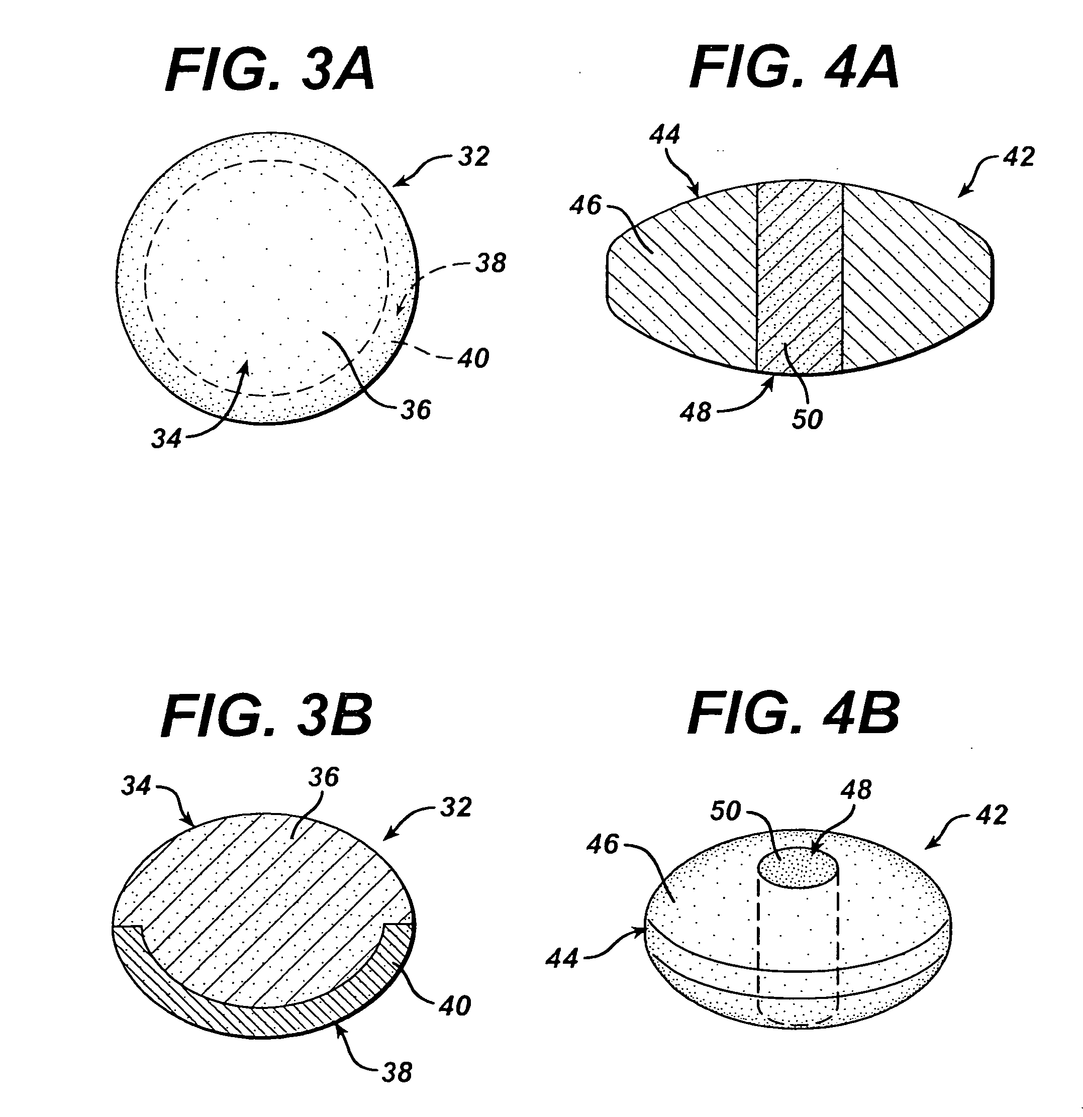
[0246] A particular advantage of the present invention is that either the first molded portion or second portion may be larger in cross-section (in at least one location) than the opening to the cavity within the second portion or first molded portion, respectively, which receives the first portion or second portion. In contrast, in the prior art an insert must be no larger in cross-section than the opening of the cavity which receives the insert. In a preferred embodiment of this invention, the first molded portion or a part thereof is received by a cavity located within the second portion. Thus, the first molded portion forms a “tongue” which interlocks with the cavity or “groove” within the second portion. This may also be expressed in terms of the “draft angle” of the second portion. As used herein, the term “draft angle” refers to the angle defined by the side wall of the cavity and a line perpindicular to the face of the inserted (e.g. first) portion, as described for example in Rosato et al., Injection Molding Handbook, pp. 601-04, (2d ed. 1995), the disclosure of which is incorporated herein by reference. In the present invention, the draft angle of the second portion may have a value less than zero. However, in the prior art compositions, the draft angle must have a zero or positive value.
[0247] In another embodiment of this invention, at least one exterior surface of the first portion is flush with at least one exterior surface of the second portion.
[0248] This invention will be further illustrated by the following examples, which are not meant to limit the invention in any way.

Problems solved by technology

It is possible, via compression-coating, to produce a 2-portion shell, which may function as a barrier, or release delaying coating; however compression-coated systems are limited by the shell thickness and shell composition as well as processing costs.
One limitation of such assemblies is the propensity for the two portions to become detached due to inadequate adherance and minimal surface area of contact between them.
Such assemblies are additionally limited in the types of geometries that are possible at the interface.
Too little waxy material will lead to insufficient bonding of the filling material; too much waxy material the filling material will bond too strongly to the tablet surface and consequently will be difficult to remove afterwards.
The technique is limited to colored articles and only allows the use of optically anisotropic filling materials.
However, the method disclosed in EP 088,556 has several problems.
First, it has been found that the adhesion of the powdery material to the intagliations is not satisfactory as the material shows a tendency to loosen and fall out.
This problem arises particularly when an outer coating film is applied to the filled tablet and the loosened material becomes fixed in the outer coating film, thus yielding speckled tablets.
Addition of a wax to the powdery material to improve adhesion, on the other hand, adversely affects the distribution of the powdery material in that more of it sticks to the surface of the tablet and is difficult to remove.
Several other drawbacks are associated with the use of a wax in the dry powdery material.
In particular the necessity to heat the tablets filled with a wax and a powdery material to melt the wax poses a barely acceptable risk since many medicines are thermolabile and might deteriorate significantly in the process.
Further, it is difficult to evenly dye a dry mixture of a wax and a powdery material, which in turn puts a limitation on the effectively possible color combinations.
All of the methods described above for producing a dosage form having one or more separate portions are relatively costly, complex, and time-intensive.
Additionally, known methods for producing filled-in intagliations are limited in terms of suitable materials and the obtainable surface configurations and appearance of the resultant dosage form.
Besides the above-mentioned limitations on the fill material itself, the tablet subcoating must be non-adhesive enough for the fill-in material to rub off upon tumbling in a hot coating pan.
These methods cannot produce filled-in intagliations having the fill material raised above the tablet surface, or even perfectly flush with the tablet surface.
Another significant challenge in the pharmaceutical industry is the opportunity to minimize manufacturing and packaging costs through standardization.
All of the prior art methods for forming a shell on a core share the common limitation of having the shape of the shell depend upon and generally conform to the shape of the core.
Other limitations shared by conventional encapsulation and enrobing processes include high cost and complexity, limitations on the thickness of the coating or shell, and the creation of raised seams between capsule halves and / or coatings.
In addition, the separation of incompatible ingredients in pharmaceutical dosage forms presents a significant challenge to the formulator.
This challenge has primarily been addressed in the art through the use of relatively costly and time-intensive methods of coated particles, multiple layer compressed tablets, or compression coating.
Another significant challenge in the formulation of pharmaceutical dosage forms is that of providing multiple release profiles for multiple active ingredients.
This challenge has primarily been addressed in the art through the use of coated particles, or sprayed or compressed tablet coatings, all of which add cost and complexity to the manufacturing process.
However, a limitation of such assemblies is the propensity for the two portions to become detached due to inadequate adherance and minimal surface area of contact therebetween.
Such assemblies are additionally limited in the types of geometries that are possible at the interface.

Method used


Image

  • Composite dosage forms
  • Composite dosage forms
  • Composite dosage forms

Examples


example 1

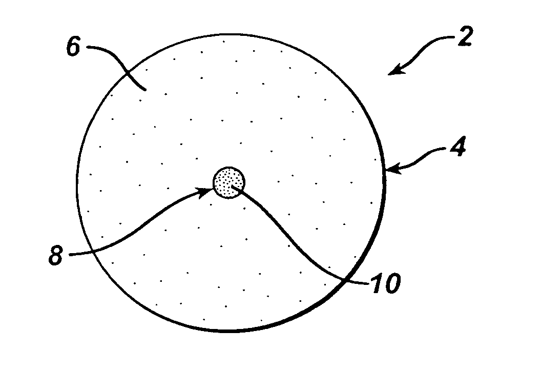
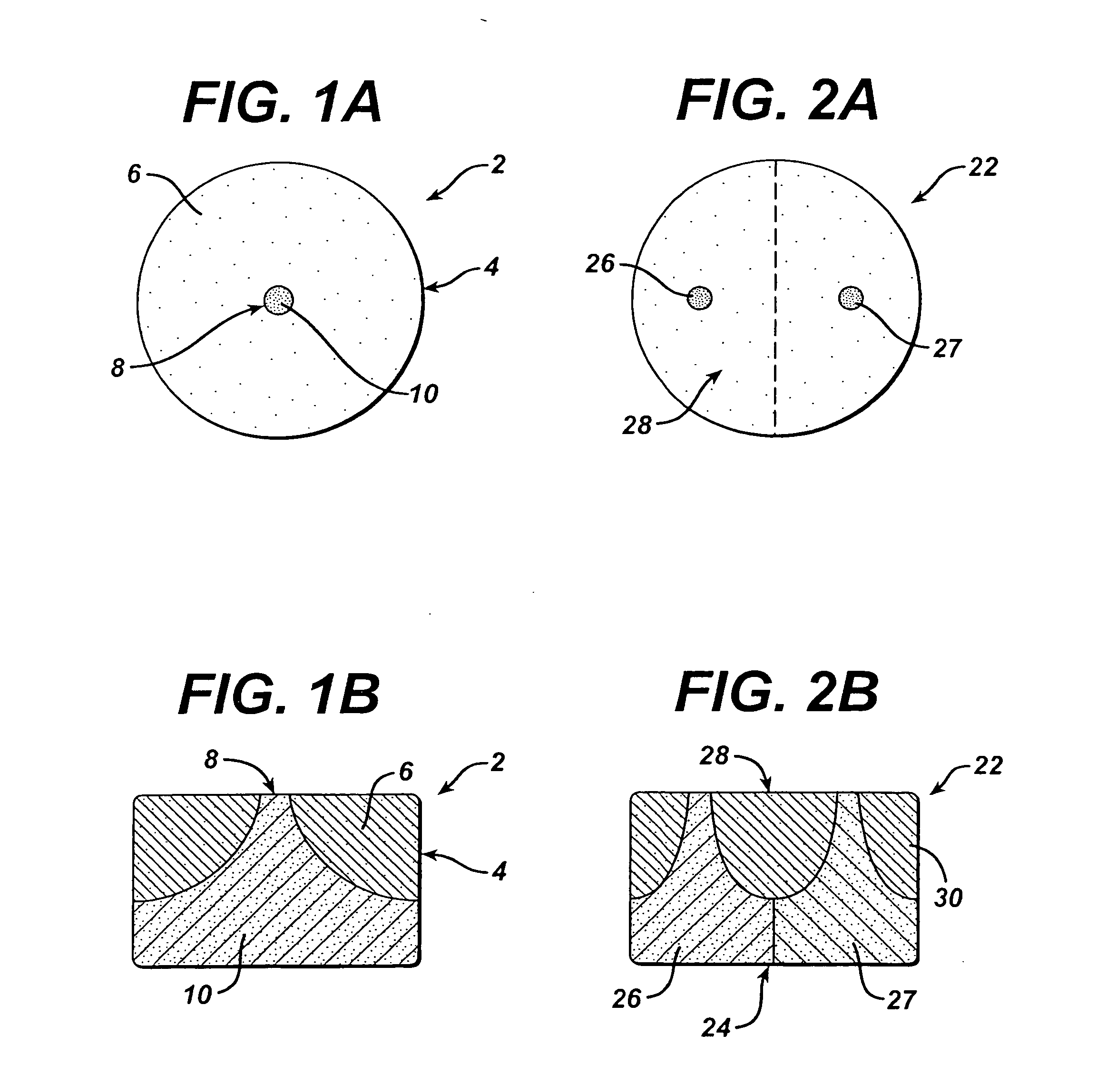
[0249] Dosage forms of the invention are made in a continuous process using an apparatus comprising a thermal cycle molding module and a compression module linked in series via a transfer device as described at pages 14-16 of copending U.S. application Ser. No. 09 / 966,939, the disclosure of which is incorporated herein by reference. The dosage forms have the structure shown in FIGS. 1A and 1B and comprise a first portion comprising a first molded material and a second portion comprising a second material that is compressed.

[0250] The first portions are made of a flowable material comprising the following ingredients:

WeightMg / TabletTrade NameManufacturer%TabletPolyethyleneCarbowax ®Union Carbide60.3190Glycol 3350Corporation,Danbury, CTCroscarmelloseAc-Di-Sol ®FMC Corporation,30.195SodiumNewark, DEPseudoephedrineBASF9.530HydrochloridePharmaChemikalienCrystalGmbH & Co.,Ludwigshafen / Rhein.

[0251] The second portions are made of a dry blend comprising the following ingredients: acetami...


PUM

PropertyMeasurementUnit
diameteraaaaaaaaaa
depthaaaaaaaaaa
thicknessaaaaaaaaaa

Abstract

A composite dosage form comprises at least one active ingredient, a first portion comprising a first molded material, and a second portion comprising a second material which is compositionally different from the first material. The first and second portions are joined at an interface, and a surface of the first portion at the interface resides substantially conformally upon a surface of the second portion of the interface. Either the first portion, the second portion, or a combination thereof may contain at least one active ingredient. The first portion, second portion or both may also each comprise an insert which may contain at least one active ingredient. The dosage form may also comprise a third portion which is located between the first and second portions.

Description

BACKGROUND OF THE INVENTION [0001] 1. Field of the Invention [0002] This invention relates to composite dosage forms such as pharmaceutical compositions. More particularly, this invention relates to composite dosage forms comprising at least one active ingredient and having a first portion comprising a first molded material and a second portion comprising a second material, in which the second material is compositionally different than the first material, surfaces of the first and second portions are joined at an interface, and the first portion surface at the interface resides substantially conformally upon the second portion surface at the interface. [0003] 2. Background Information [0004] Dosage forms having two or more distinct portions are useful in the pharmaceutical arts for overcoming a number of commonly encountered challenges, including the separation of incompatible active ingredients, achieving acceptable content uniformity of a low-dose / high potency active ingredient, d...

Claims


Application Information

Patent Timeline
Patent Type & Authority Applications(United States)
IPC IPC(8): A23G1/00A23G3/34A23G1/54A23G3/00A23G3/04A23G3/36A23G3/54A23L1/00A23L1/09A23L1/30A61J3/00A61J3/06A61J3/10A61K9/00A61K9/14A61K9/20A61K9/22A61K9/24A61K9/26A61K9/28A61K9/30A61K9/32A61K9/34A61K9/36A61K9/38A61K9/48A61K9/50A61K31/136A61K31/137A61K31/277A61K47/10A61K47/14A61K47/26A61K47/30A61K47/32A61K47/34A61K47/36A61K47/38A61K47/44A61K47/46A61P11/00B30B11/08B30B11/34B30B15/30G06F17/30
CPCA23G1/54Y10T428/1352A23G3/04A23G3/368A23G3/54A23L1/09A61J3/005A61J3/06A61J3/10A61K9/0004A61K9/0056A61K9/2013A61K9/2018A61K9/2027A61K9/2031A61K9/2054A61K9/2068A61K9/2072A61K9/2081A61K9/209A61K9/2095A61K9/282A61K9/2826A61K9/284A61K9/286A61K9/2873A61K9/2886A61K9/2893A61K9/5084B30B11/08B30B11/34B30B15/302A23G3/0029A23L29/30A61P11/00A61P43/00A61K9/28
Inventor SOWDEN, HARRY S.BUNICK, FRANK J.MCNALLY, GERARD P.LEE, DER-YANGTHOMAS, MARTIN
Owner MCNEIL PPC INC
Learn More