
Methods and systems for holographic data recovery

a technology of holographic data and storage methods, applied in the field of holographic data storage methods and systems, can solve the problems of slm, detector, storage medium, etc., and may become misaligned with various other components of the particular system, and may affect the and the detection accuracy of the data recovery process is improved.

Inactive Publication Date: 2005-01-27
AKONIA HOLOGRAPHICS
View PDF15 Cites 40 Cited by
  • Summary
  • Abstract
  • Description
  • Claims
  • Application Information

AI Technical Summary

Benefits of technology

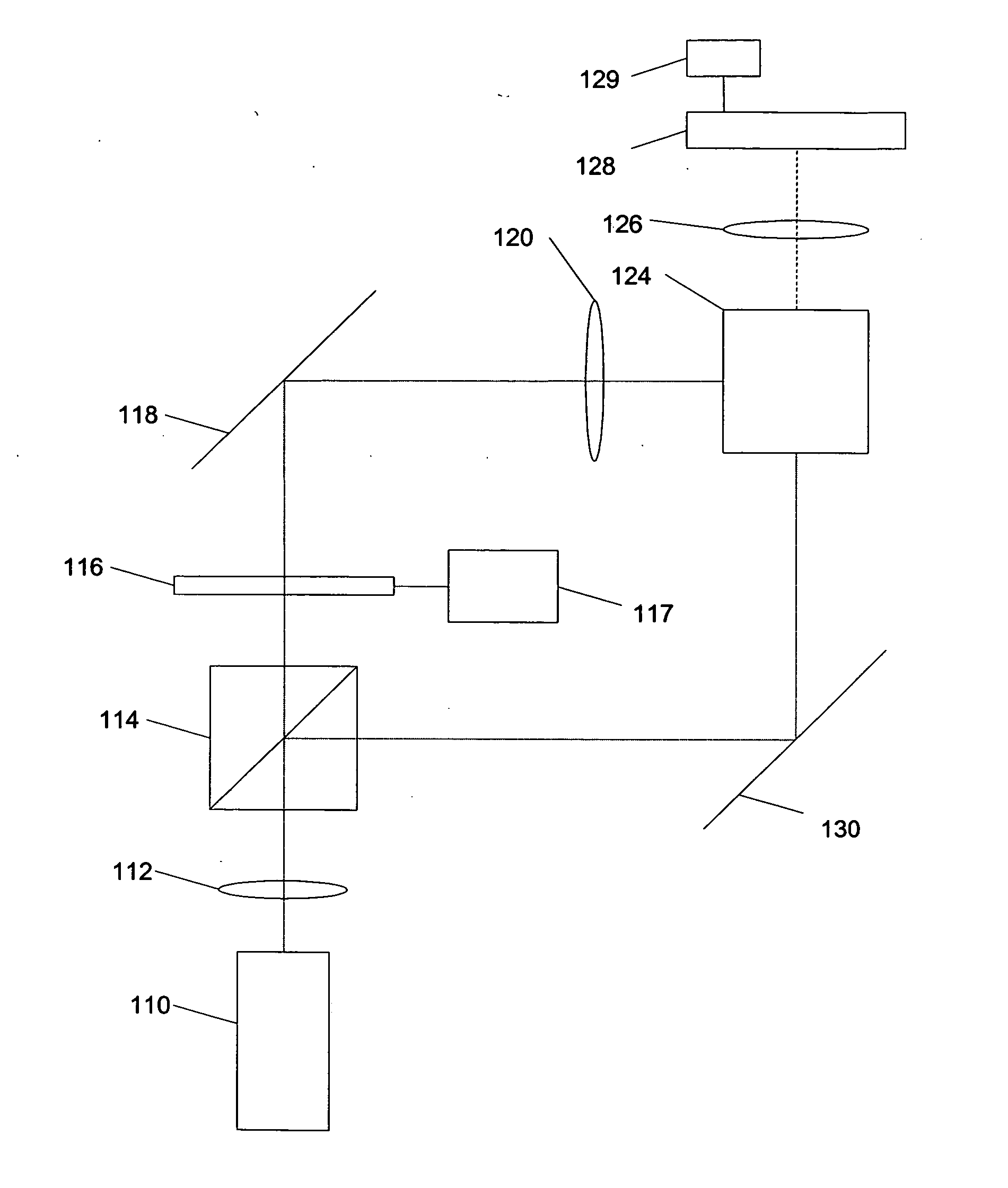
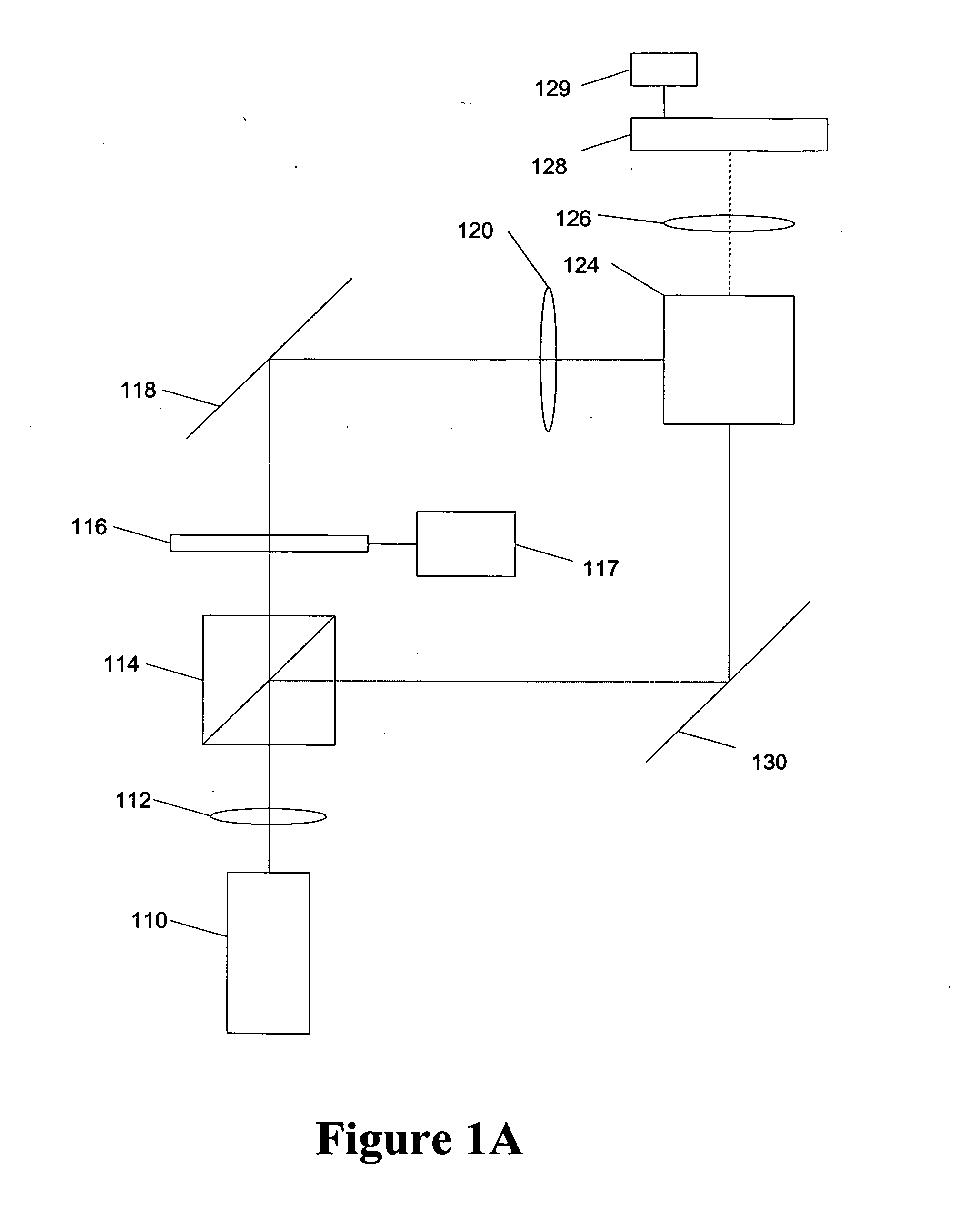
The patent describes a method and system for holographic storage and data recovery. The method involves detecting a stored image and oversampling it using a detector with small pixel sizes. Pixel information from the source image is then obtained using a fractional delay filter. The system includes an image processor that recovers the holographic stored data by detecting and converting the sample rate of the image. The technical effects of this invention include improved data recovery and reduced latency in holographic storage systems.

Problems solved by technology

Over time, however, the SLM, detector, or storage medium may become misaligned with various other components of the particular system.
For example, temperature change, vibration, shock, and the like may result in slight movements or deformations of the detector, SLM, storage medium, or other optical components.
The result may be translational, tilt, or rotational misalignment of the detector with the storage medium or the SLM.
Further, in systems with removable storage media, such as a rotating disk or rectangular storage media, the media may be misaligned when inserted into one or more systems for read and / or write operations.
Such matching is difficult to achieve in low cost high volume processes.
For example, these constraints on pixel matching may result in a holographic drive system generally having a higher cost, larger size, with increased error rates, and lower storage capacity than otherwise possible.
Deficiencies of these and other various methods include, for example, that system parameters are generally known or determined very precisely.
Some image processing techniques are computationally intensive, may require repeated iterations to converge, suffer from error propagation, and may require channel transfer characteristics, i.e., point spread functions as it varies over the image.

Method used


Image

  • Methods and systems for holographic data recovery
  • Methods and systems for holographic data recovery
  • Methods and systems for holographic data recovery

Examples


Embodiment Construction

[0024] Exemplary methods and systems are provided for holographic data recovery by oversampling. The following description is presented to enable any person skilled in the art to make and use the invention. Descriptions of specific techniques and applications are provided only as examples. Various modifications to the examples described herein will be readily apparent to those skilled in the art, and the general principles defined herein may. be applied to other examples and applications without departing from the spirit and scope of the invention. Thus, the present invention is not intended to be limited to the examples described and shown, but is to be accorded the widest scope consistent with the principles and features disclosed herein.

[0025] In a holographic data storage system, the SLM is typically aligned with the detector (or camera) such that each pixel on the SLM is projected onto a single pixel on the detector. This alignment is important for a single hologram or a group...


PUM

PropertyMeasurementUnit
rotationaaaaaaaaaa
pixel sizeaaaaaaaaaa
refractive indexaaaaaaaaaa

Abstract

A method for holographic storage data recovery in a holographic storage system is presented. One exemplary method includes detecting a stored image at a detector such that the image is oversampled. A relationship is determined between a location of the detected image and a location of the source image. Pixel information associated with the source image may be obtained from the detected image based on a fractional delay filter. In one example, the image may be oversampled by magnifying the detected image at the detector and / or having a detector with pixel sizes and spacing less than the image pixel size. Further, coefficients of the fractional delay filter may be determined, at least in part, on magnification and shift information of the image based on known registration marks.

Description

CROSS REFERENCE TO RELATED APPLICATION [0001] The present application claims benefit of earlier filed provisional patent application, U.S. Application No. 60 / 469,574, filed on May 9, 2003, and entitled “METHODS AND SYSTEMS FOR HOLOGRAPHIC DATA RECOVERY,” which is hereby incorporated by reference as if fully set forth herein.BACKGROUND [0002] 1. Field of the Invention [0003] The invention relates generally to holographic data storage methods and systems, and more particularly to methods and systems for holographic data storage recovery by oversampling and fractional-delay filter interpolation. [0004] 2. Description of the Related Art [0005] Holographic data storage systems store information or data based on the concept of a signal beam interfering with a reference beam at a holographic storage medium. The interference of the signal beam and the reference beam creates a holographic representation, i.e., a hologram, of data elements as a pattern of varying refractive index and / or absor...

Claims


Application Information

Patent Timeline
Patent Type & Authority Applications(United States)
IPC IPC(8): G03H1/22G11B7/0065
CPCG03H1/22G03H2210/20G03H1/2249G11B7/0065
Inventor PHARRIS, KENTON J.
Owner AKONIA HOLOGRAPHICS
Learn More