Handheld tester for starting/charging systems
a technology of starting/charging system and tester, which is applied in the direction of mechanical equipment, machines/engines, instruments, etc., can solve the problems of cumbersome user interface, limited user input capability of devices with limited user input capability, and limited display capability, so as to improve the starting/charging test
- Summary
- Abstract
- Description
- Claims
- Application Information
AI Technical Summary
Benefits of technology
Problems solved by technology
Method used
Image
Examples
embodiment 128
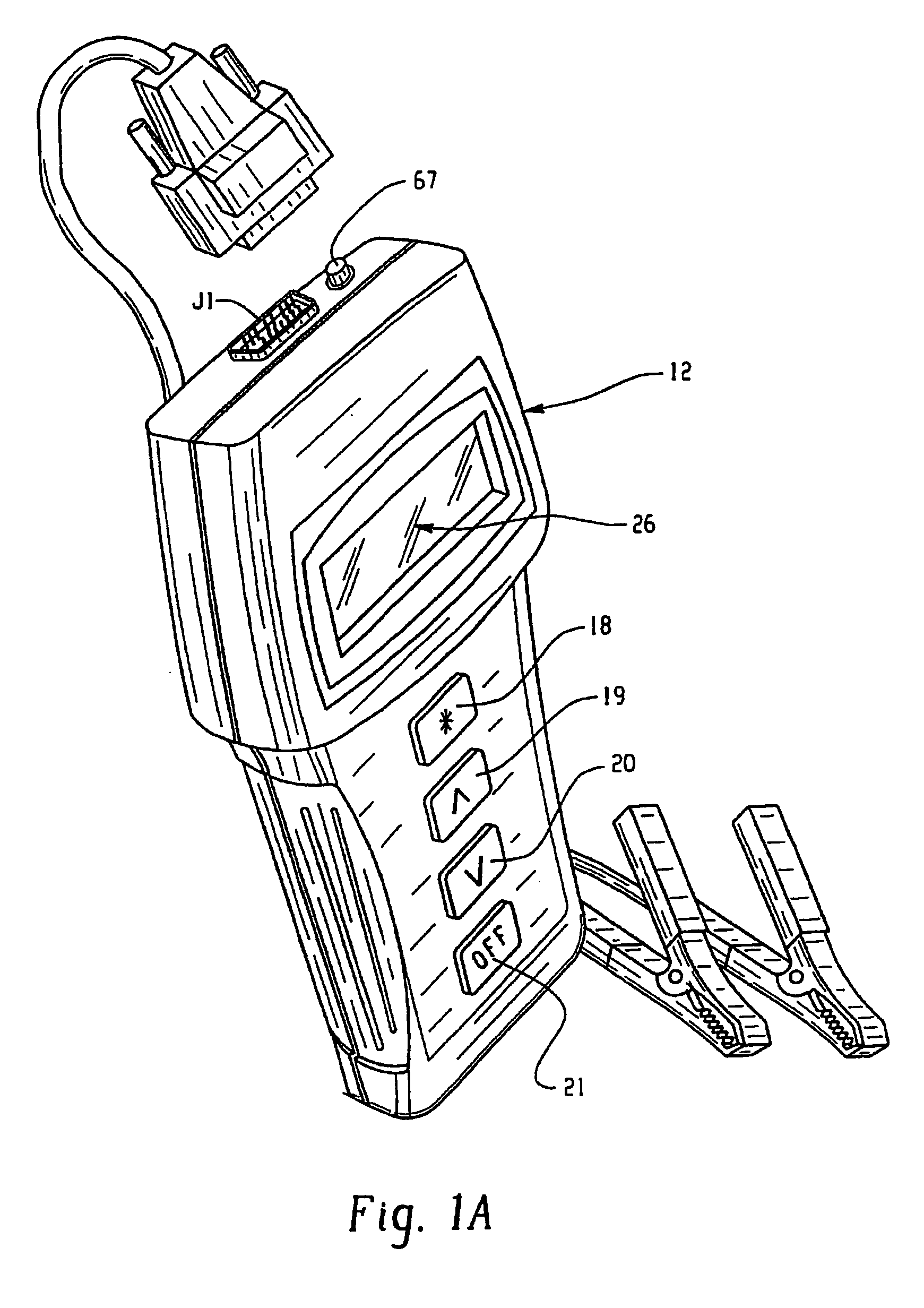
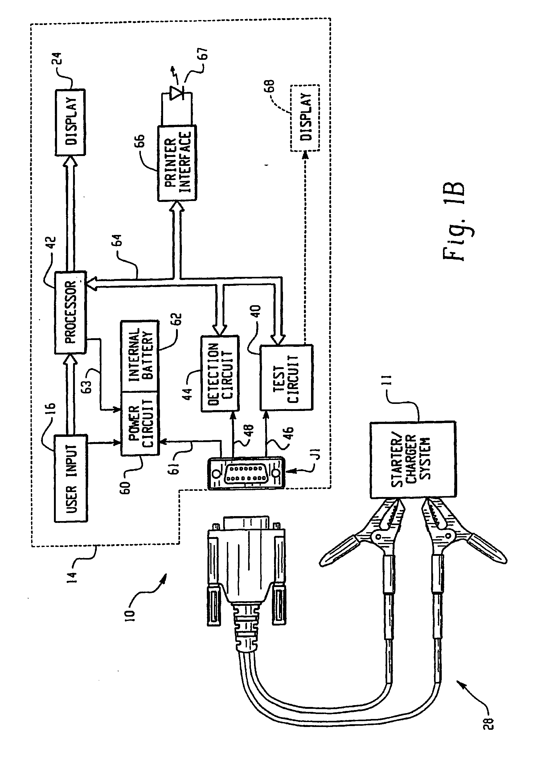
Referring now to FIGS. 5A-5C, a two-clamp embodiment 128 of a test cable 28 is shown. The cable 128 of this embodiment preferably comprises a four-conductor cable 130 in circuit communication with a connector 132 at one end, connected as shown in FIGS. 5B and 5C, and in circuit communication with a pair of hippo clips 134, 136 at the other end. The cable 128 is preferably about three (3) feet long, but can be virtually any length. The connector 132 mates with connector J1 of tester 10. The four conductors in cable 130 are preferably connected to the hippo clips 134, 136 so as to form a Kelvin type connection, with one conductor electrically connected to each half of each hippo clip, which is known in the art. In this cable 128, the power ground 94 and signal ground 96 are preferably connected to form a star ground at the negative battery terminal. Resistor R128 connects between the +sense and −sense lines. In test cable 128, pin four (4) is open; therefore, the equivalent circuit of...
embodiment 328
Referring now to FIGS. 7A-7C, a probe embodiment 328 of a test cable 28 is shown. The cable 328 of this embodiment preferably comprises a two-conductor cable 330 in circuit communication with a connector 332 at one end, connected as shown in FIGS. 7B and 7C, and in circuit communication with a pair of probes 334, 336 at the other end. The cable 328 is preferably about three (3) feet long, but can be virtually any length. The connector 332 mates with connector J1 of tester 10. In this cable 328, the power ground 94 and signal ground 96 are connected by connection 338 inside housing 340 of connector 332 to form a star ground inside housing 340. In cable 328, the battery power signal 61 is open and the detection signal 48 (pin four (4) of connector J1) is open; therefore, the equivalent circuit of the detection circuit 44 for this cable 328 is found in FIG. 3F. More specifically, with connector 332 connected to mating connector J1 on tester 10, the equivalent circuit of the detection c...
PUM
 Abstract
Description
Claims
Application Information
 - R&D
- Intellectual Property
- Life Sciences
- Materials
- Tech Scout
- Unparalleled Data Quality
- Higher Quality Content
- 60% Fewer Hallucinations
Browse by: Latest US Patents, China's latest patents, Technical Efficacy Thesaurus, Application Domain, Technology Topic, Popular Technical Reports.
© 2025 PatSnap. All rights reserved.Legal|Privacy policy|Modern Slavery Act Transparency Statement|Sitemap|About US| Contact US: help@patsnap.com


