
High resolution image reconstruction

a high-resolution, image-reconstruction technology, applied in the field of digital image processing, can solve the problems of not allowing large-scale printing of captured low-resolution images, affecting the accuracy of image reconstruction,

Active Publication Date: 2005-01-20
DOLBY INT AB
View PDF55 Cites 156 Cited by
  • Summary
  • Abstract
  • Description
  • Claims
  • Application Information

AI Technical Summary

Benefits of technology

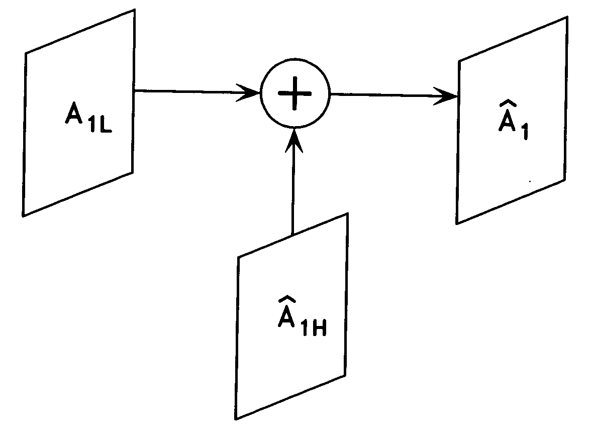
[0006] The present disclosure is generally directed to a high resolution image reconstruction method, comprising generating at least one image sequence of temporally related high and low resolution image frames, each of the high resolution image frames including a low spatial frequency component and a high spatial frequency component; using spatial interpolation to generate a low spatial frequency component from a low resolution image frame of the image sequence; generating a high spatial frequency component from at least one high resolution image frame of the image sequence, the high resolution image frame being closely related to the low resolution image frame; remapping the high spatial frequency component to a motion-compensated high spatial frequency component estimate of the low resolution image frame; and adding the motion-compensated high spatial frequency component estimate of the low resolution image frame to the generated low spatial frequency component of the low resolution image frame to form a reconstructed high resolution image of the low resolution image frame.

Problems solved by technology

The estimate, however, may appear blurry as it does not incorporate any related high spatial frequency information from neighboring high-resolution image frames and, consequently, does not allow large size prints of the captured low-resolution image.
None of the known image reconstruction methods utilize high spatial frequency data from closely related high-resolution image frames.

Method used


Image

  • High resolution image reconstruction
  • High resolution image reconstruction
  • High resolution image reconstruction

Examples


Embodiment Construction

[0021] Hereinafter, some preferred embodiments of the present invention will be described in detail with reference to the related drawings of FIGS. 1-12. Additional embodiments, features and / or advantages of the invention will become apparent from the ensuing description or may be learned by practicing the invention.

[0022] The drawings are not to scale with like numerals referring to like features throughout both the drawings and the description.

[0023] The following description includes the best mode presently contemplated for carrying out the invention. This description is not to be taken in a limiting sense, but is made merely for the purpose of describing the general principles of the invention.

[0024] Current CMOS (complementary metal-oxide semiconductor) image sensor technology allows the integration of light sensing elements and subsequent digital image signal processing. One known example of such CMOS technology allows a digital camera to switch seamlessly between high reso...


PUM


Abstract

A technique of reconstructing a high resolution image from at least one image sequence of temporally related high and low resolution image frames wherein each of said high resolution image frames includes a low spatial frequency component and a high spatial frequency component is described. The high-resolution image reconstruction technique uses spatial interpolation to generate a low spatial frequency component from a low-resolution image frame of the image sequence. The technique is adapted to generate a high spatial frequency component from at least one high resolution image frame of the image sequence which is closely related to the low resolution image frame, and to remap the high spatial frequency component to a motion-compensated high spatial frequency component estimate of the low resolution image frame. The motion-compensated high spatial frequency component estimate is added to the generated low spatial frequency component to form a reconstructed high-resolution image of the low-resolution image frame.

Description

FIELD OF THE INVENTION [0001] The present invention relates generally to digital image processing and more particularly to interpolation of a mixed resolution image sequence for high-resolution image reconstruction. BACKGROUND OF THE INVENTION [0002] Digital video processing refers to manipulation of the digital video bitstream. Some applications of digital video processing include standards conversion, image enhancement, high resolution image reconstruction, etc. [0003] One known method for high-resolution image reconstruction includes the use of spatial interpolation to produce a low spatial frequency image estimate from a captured low-resolution image frame. The estimate, however, may appear blurry as it does not incorporate any related high spatial frequency information from neighboring high-resolution image frames and, consequently, does not allow large size prints of the captured low-resolution image. [0004] Another known high-resolution image reconstruction method uses non-li...

Claims


Application Information

Patent Timeline
Patent Type & Authority Applications(United States)
IPC IPC(8): G06T3/40G06T5/50
CPCG06T3/4023G06T3/4007
Inventor SAMADANI, RAMIN
Owner DOLBY INT AB
Learn More