
Bionest reactor for the application of anaerobic wastewater treatment and bioenergy recovery

Inactive Publication Date: 2005-01-20
UNIV OF HAWAII
View PDF9 Cites 63 Cited by
  • Summary
  • Abstract
  • Description
  • Claims
  • Application Information

AI Technical Summary

Benefits of technology

[0016] In some embodiments, the reactor can include a bank of two or more housings, wherein wastewater can flow serially along a flow path through each housing in the bank. In preferred embodiments, each housing in the reactor can include at least one nest space. In some embodiments, the reactor can further include a plurality of banks of housings, wherein the banks can be arranged to permit parallel flow of wastewater in the banks, permitting multiplex passage of a large volume of wastewater through the reactor, such that substantially all of the wastewater can pass through the reactor with a substantially uniform hydraulic retention time. In some embodiments, the reactor can have an efficiency of removal of one or more organic pollutants of at least about 50% chemical oxygen demand (COD) removal at a loading rate of over 10 g / l / d and / or the efficiency can be at least about 40% chemical oxygen demand (COD) removal at a loading rate of over 20 g / l / d. In preferred embodiments, the efficiency can be between 50% and 85% COD removal at a loading rate of over 15 g / l / d.

Problems solved by technology

Likewise, similar environmental quality issues are becoming increasingly important in other countries outside the United States as well.
However, the UASB granule blanket reactors have some limitations because the granulation formulation depends on wastewater types rather than reactor design and operation (Jhung J. K. and Choi E.
For example, granule formation can be difficult to form during UASB treatment of wastewater containing a high concentration of fat and lipids such as dairy wastewater (Hawkes et al., 1995).
Accordingly, UASB methods of treating lipid-rich wastewater have often met with poor results (Hawkes et al., 1995, Perle et al.
The poor performance of UASB systems is often due to the binding of the wastewater lipids to the granules, causing breakdown of the granules.
Lipid loading rates exceeding 2-3 kg COD m−3 day−1 caused granule breakdown resulting in total sludge wash-out.
Even at lower loading rates (less than 1.5 g / l / d), the system was still unreliable because of unpredictable sludge flotation.
Additional concerns with the UASB reactors include mass transfer limitations due to sub-optimal mixing condition inside the reactor, and high upflow velocity and gas production causing granules wash-out (Driessen and Yspeert, 1999).
An increase in upflow velocity in such systems may cause too little contact time between the granule and the soluble substrate.
UASB systems are often plagued with poor reliability, particularly when used for high lipid wastewater.
The solids content accumulated in the sludge bed, which led the poor reliability of operational performance.
This inhibition of methanogenic activity resulted in poor anaerobic biodegradation of fat and lipids in the wastewater.
An additional issue with conventional wastewater treatment systems is that some systems require a heating method to control the temperature for optimal performance, particularly for wastewater having a high lipid content.
However, although heating the system may improve lipid biodegradation, the economic cost can be very high, particularly if an external heat source is not available (Petruy and Lettinga, 1997).

Method used


Image

  • Bionest reactor for the application of anaerobic wastewater treatment and bioenergy recovery
  • Bionest reactor for the application of anaerobic wastewater treatment and bioenergy recovery
  • Bionest reactor for the application of anaerobic wastewater treatment and bioenergy recovery

Examples


example 1

Analysis of an Existing, Non-bionest Wastewater Treatment: Dairy Wastewater from a Hawaiian Cattle Farm

[0119] The system parameters of an existing, nonbionest wastewater treatment facility operated in Oahu, Hawaii were measured for comparative purposes. The source of the wastewater was a 1600 head livestock farm, including 1,000 milk cows and a milk-producing facility.

[0120] Wastewater flow: 300,000 gallon / day (1,136 m3 / day).

[0121] Total COD Concentration: 4000-6500 mg / L.

[0122] Soluble COD: 1200-2000mg / L.

[0123] The discharged wastewater flowed into two receiving lagoons, each with the following dimensions: 50×250×6 ft3 (15.24×76.2×1.83 m3). The effluent was discharged to 10 acres of land planted with California Grass.

[0124] The source and characteristics of the dairy wastewater generated from the diary farm are indicated below in Table 4. The various types of wastewater present in the dairy farm were analyzed to determine TCOD, SCOD, N, P, TSS, and VSS. Total COD, soluble COD,...

example 2

Reactor Set Up and Startup

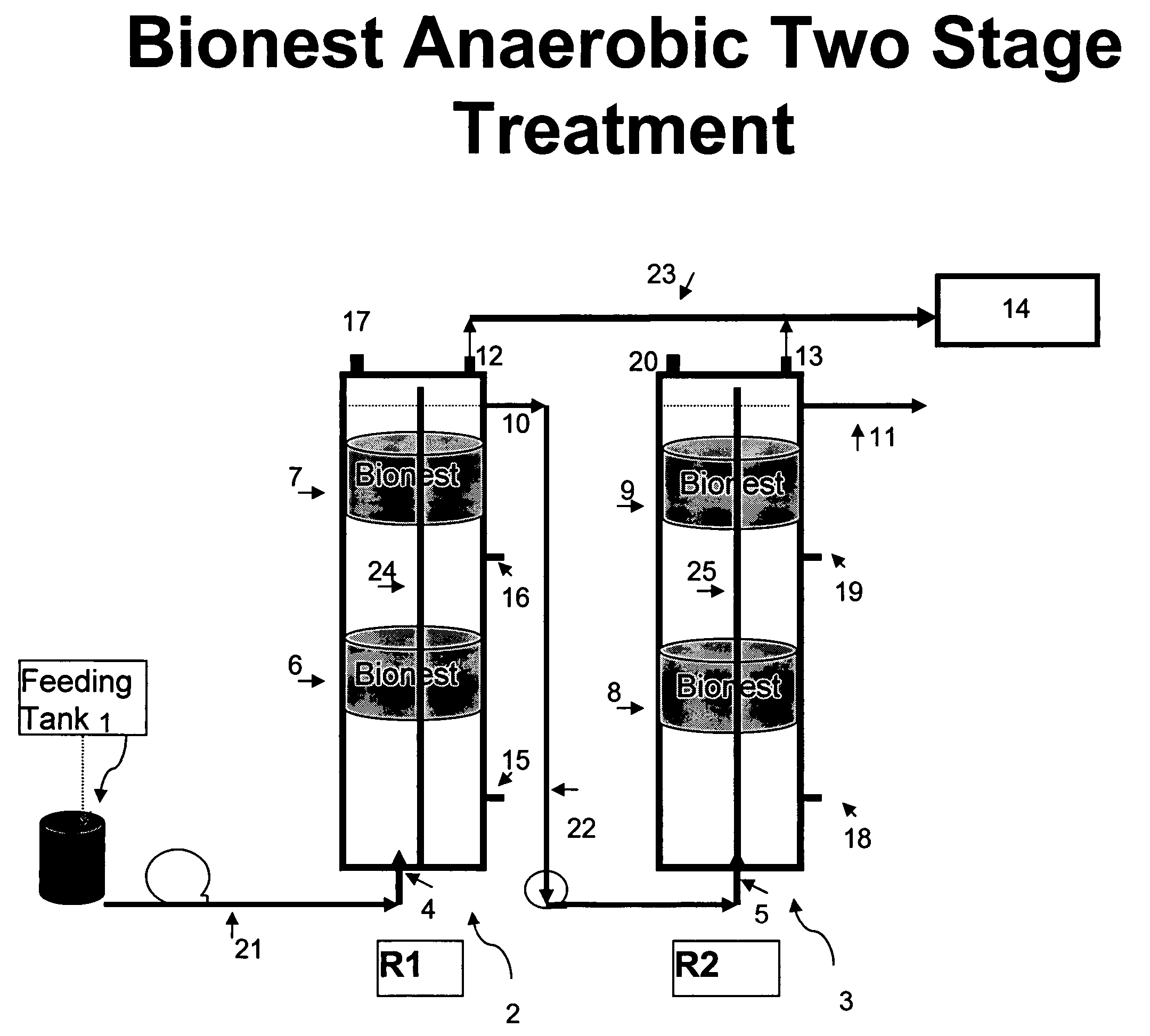
[0126] The apparatus was set up according to FIG. 3. A two-stage bioreactor (10 liter each) as shown in FIG. 5, was designed and filled with two bionest bioreactors connected in series by tubing. Each individual bioreactor contained two bionest units. They were filled with two layers of medium resulting in 98% void volume in the reactor. The reactor was made of transparent PVC in order to be able to observe the sludge formation and accumulations. Three sample outlets were designed to test the sludge distribution at the different heights of 15 cm, 65 cm and 90 cm, respectively. A special puncture needle was designed to take samples from the bionest. Table 5 shows the main parameters of the two-stage bionest reactors and bionest content. FIG. 1 shows an example of the bionest structure, FIG. 3 shows a diagram of the two-stage anaerobic bioreactor, and FIG. 4 shows a diagram of the two-stage anaerobic reactor plus an aerobic bioreactor. FIG. 5 is a photograph...

example 3

Operating the Bionest Bioreactor

[0129] The bionest system was set up as in Example 2, above. Milk parlor wastewater was collected and stored in a refrigerator (about 4° C.) prior to use. This chilling was for convenience and reproducibility of starting material. In operation there is no need to pre-chill the wastewater. The stored wastewater was fed into reactor directly from the refrigerator. Seeded sludge was collected from an existing anaerobic reactor operated by batch. In order to test the sludge distribution in the bionest bioreactor, and to compare the effects of various operation schedules, sludge from the bioreactor was sampled both at the start of the feeding period and at the end of the feeding period. Sludge sampling was collected from the sampling outlets of various heights. The sludge samples were removed from the bionest bioreactor using a long puncture needle connected with a vacuum ball. A single stage reactor having the same sludge content as in the bionest biorea...


PUM

PropertyMeasurementUnit
Fractionaaaaaaaaaa
Fractionaaaaaaaaaa
Fractionaaaaaaaaaa

Abstract

A method of treating wastewater using an anaerobic bioreactor which contains a “bio-nest” structure to retain the microbial content and improve digestion efficiency is disclosed. The bionest system results in a longer SRT, good sludge mixing, and reduced wash-out of sludge. The system is particularly useful for treatment of lipid rich wastewater such as dairy wastewater.

Description

RELATED APPLICATIONS [0001] This application claims priority under 35 U.S.C. §119 to U.S. Provisional Application No. 60 / 480,085, filed Jun. 19, 2003, the disclosure of which is hereby incorporated by reference in its entirety.GOVERNMENT INTEREST IN THE INVENTION [0002] Certain aspects of the invention disclosed herein were made with United States government support under USDA (U.S. Department of Agriculture) Grant No. HATCH-550. The United States government has certain rights in these aspects of the invention.BACKGROUND OF THE INVENTION [0003] 1. Field of the Invention [0004] The invention generally relates to the field of wastewater treatment. A method of treating wastewater using an anaerobic bioreactor which contains a “bio-nest” structure to retain the microbial content and improve digestion efficiency is disclosed. The system is particularly useful for treatment of lipid rich wastewater. [0005] 2. Description of the Related Art [0006] Improvement of the wastewater treatment pr...

Claims


Application Information

Patent Timeline
IPC IPC(8): C02FC02F3/28
CPCC02F3/2806Y02E50/343C02F2103/327C02F3/286Y02E50/30
Inventor DONG, LIANGJIEYANG, PING-YI
Owner UNIV OF HAWAII
Learn More