
Distillation apparatus

a technology of distillation apparatus and flue, which is applied in the direction of auxilaries, coke oven details, water/sludge/sewage treatment, etc., can solve the problems of not being able to automatically repeat the distillation process, the receiving tank is not easily separable and replaceable from the object cleaning apparatus, and the need to periodically change the oil, so as to improve the heat conductivity of the tank, improve the draining of debris, and ease the removal of said debris

Inactive Publication Date: 2005-01-20
UNI RAM CORP
View PDF9 Cites 27 Cited by
  • Summary
  • Abstract
  • Description
  • Claims
  • Application Information

AI Technical Summary

Benefits of technology

[0013] In accordance with a further aspect of the invention a fluid distillation apparatus, the duty tank, and the receiving tank are built into the object cleaning apparatus in such way that any one of said three components can be removed from and re-installed to the object cleaning apparatus easily and within a short period of time.
[0040] In accordance with a further aspect of the invention there is provided a distillation chamber for use with fluid distillation apparatus and in particular an auto repeating fluid distillation apparatus, the tank having improved means to remove accumulated debris from the tank. This feature may be used in the auto-repeating recycler of this invention but is also useful Where the debris is not liquid and must be removed manually. This design may be used in a fluid distillation apparatus which is not automatically repeating or which automatically repeats the distillation cycle up to two or three times only. If it is repeating 3 cycles, the boiling temperature is lowered by 20 to 30° C. during the first two cycles so that the debris still contains some fluid and does not solidify. In the last cycle, the temperature is raised and additional heating time is provided to help solidify the debris and thus ease the removal of said debris.

Problems solved by technology

Typically, the built-in fluid distillation apparatus, the duty tank, or the receiving tank is not easily separable and replaceable from the object cleaning apparatus.
Typically the built-in distillation apparatus is for a batch distillation process and is not capable of automatically repeating the distillation process.
The built-in distillation apparatus typically does not employ electrically actuated (intrinsically safe) solenoid valves to control pneumatic devices required for automatic distillation operations.
The built-in distillation apparatus is designed to drain waste debris manually and does not employ pneumatically actuated valve for automatically draining waste debris from the distillation chamber.
It is further known that typical distillation apparatus comprises a distillation tank which is heated indirectly through oil jacket which surround the distillation tank, thereby causing a need to periodically change said oil.
It is further known that typical distillation apparatus are not capable of distilling a mixture of fluids and automatically separating the distilled fluids to more than one receiving container.
It is further known that typical distillation apparatus are not equipped with a means capable of one-way or two-way communication with any remote devices such as remote alarm apparatus, remote fire extinguisher, remote diagnostic apparatus.

Method used


Image

  • Distillation apparatus
  • Distillation apparatus
  • Distillation apparatus

Examples


Embodiment Construction

[0064] The following description, by way of example, describes and illustrates each aspect of the invention mentioned above.

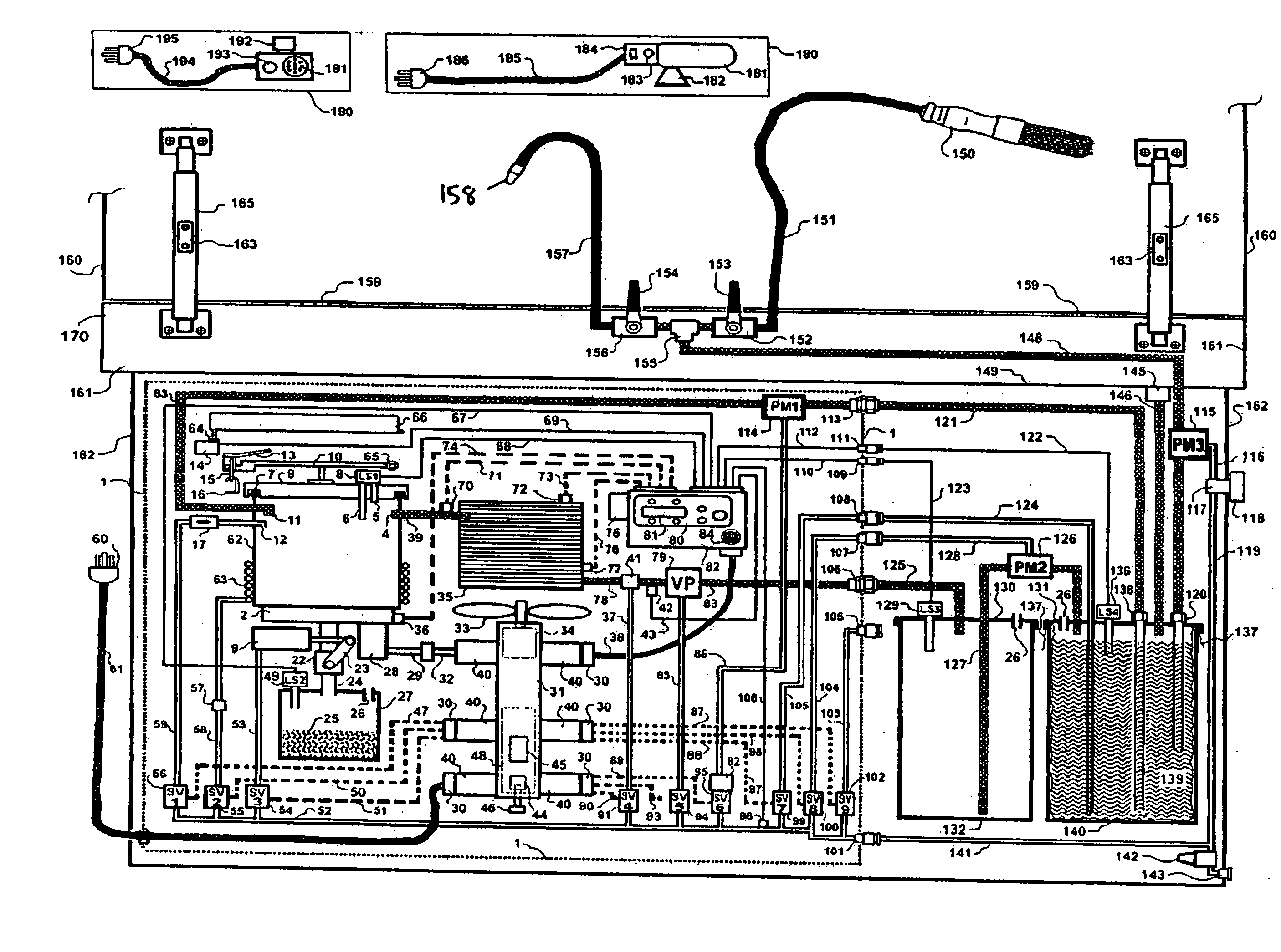
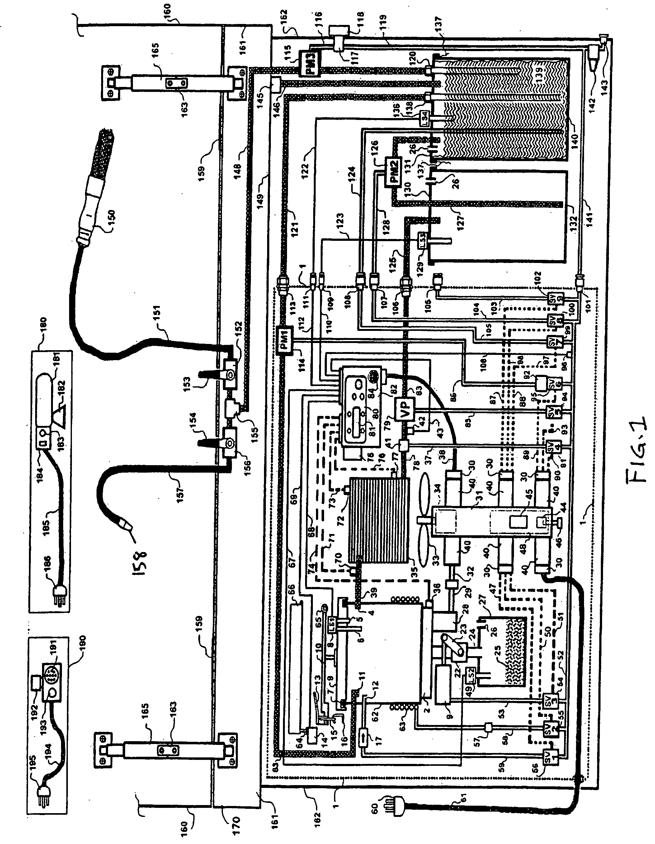
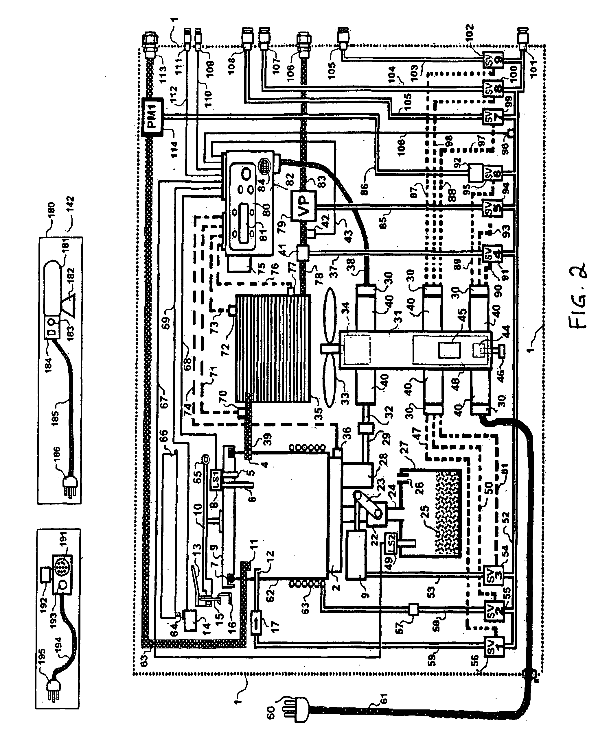
[0065] Shown in FIG. 1 is an embodiment of a fluid distillation apparatus adapted for use with a manual object cleaning apparatus. In the embodiment shown in FIG. 1, an automatic repeating fluid distillation apparatus 1 is adapted to the Manual Object cleaning apparatus 170. The recycler and the object cleaning apparatus are preferably electrically and pneumatically powered, so that the fluid 139 in the Duty tank 140 contaminated through the use of the Manual Object cleaning apparatus 170 may be automatically distilled by the Fluid distillation apparatus 1 when required.

[0066] The Fluid distillation apparatus 1 is installed inside the Base Cabinet 162 of the Manual Object cleaning apparatus 170 and is connected to the various parts of the Manual Object cleaning apparatus 170 at inside of the Base Cabinet 162 by means of connectors 105, 106, 107, 108, 109, 111...


PUM

PropertyMeasurementUnit
Widthaaaaaaaaaa
Widthaaaaaaaaaa
Widthaaaaaaaaaa

Abstract

A fluid distillation apparatus is removably built into a object cleaning apparatus which comprises a duty tank for retaining contaminated fluid, a receiving tank for receiving the distilled fluid from the distillation apparatus and a sink means in which the objects are cleaned. The fluid distillation apparatus comprises at least one each of a fluid inlet port through which the fluid to be distilled is transferred from a container containing the fluid to be distilled to distillation chamber, a fluid outlet port through which the distilled fluid is transferred to a container to hold the distilled fluid, an air supply port to which compressed air supply is to be connected, a power cord through which the electric power is supplied, preferably an outlet through which air pressure for fluid agitation is supplied to the said container containing the fluid to be distilled, and preferably an outlet through which air pressure is supplied to a pump means for transferring the distilled fluid from the receiving container to the duty fluid container. The fluid distillation apparatus, duty tank, and the receiving tank are built into the object cleaning apparatus in such way that any one of these components can be easily removed from and re-installed to the object cleaning apparatus.

Description

FIELD OF INVENTION [0001] This invention relates to fluid distillation apparatus and in particular to fluid distillation apparatus programmed to perform automatic distillation processes. BACKGROUND OF THE INVENTION [0002] It is known to provide fluid distillation apparatus which is built into a object cleaning apparatus comprising a duty tank for retaining a contaminated fluid, a receiving tank for accepting a distilled fluid from the fluid distillation apparatus and a sink means in which objects are cleaned. Typically, the built-in fluid distillation apparatus, the duty tank, or the receiving tank is not easily separable and replaceable from the object cleaning apparatus. Typically the built-in distillation apparatus is for a batch distillation process and is not capable of automatically repeating the distillation process. [0003] The built-in distillation apparatus typically does not employ electrically actuated (intrinsically safe) solenoid valves to control pneumatic devices requ...

Claims


Application Information

Patent Timeline
IPC IPC(8): B08B1/00B01D1/00B01D3/00B01D3/10B01D3/42B01D5/00B08B3/00B08B3/02B08B3/04C02F1/04C23G5/04
CPCB01D1/0017B01D3/10B01D3/42C23G5/04B08B3/006B08B3/02C02F1/048B01D5/0051Y10S203/19
Inventor YAMAMOTO, SOICHIRO
Owner UNI RAM CORP
Learn More