
Medical device interface system and method

a medical device and interface technology, applied in the field of programming devices, can solve problems such as error messages, difficulty in physicians dealing with non-compatibility of programming, and increasing complexity of icds to program

Active Publication Date: 2005-01-13
CARDIAC PACEMAKERS INC
View PDF12 Cites 64 Cited by
  • Summary
  • Abstract
  • Description
  • Claims
  • Application Information

AI Technical Summary

Benefits of technology

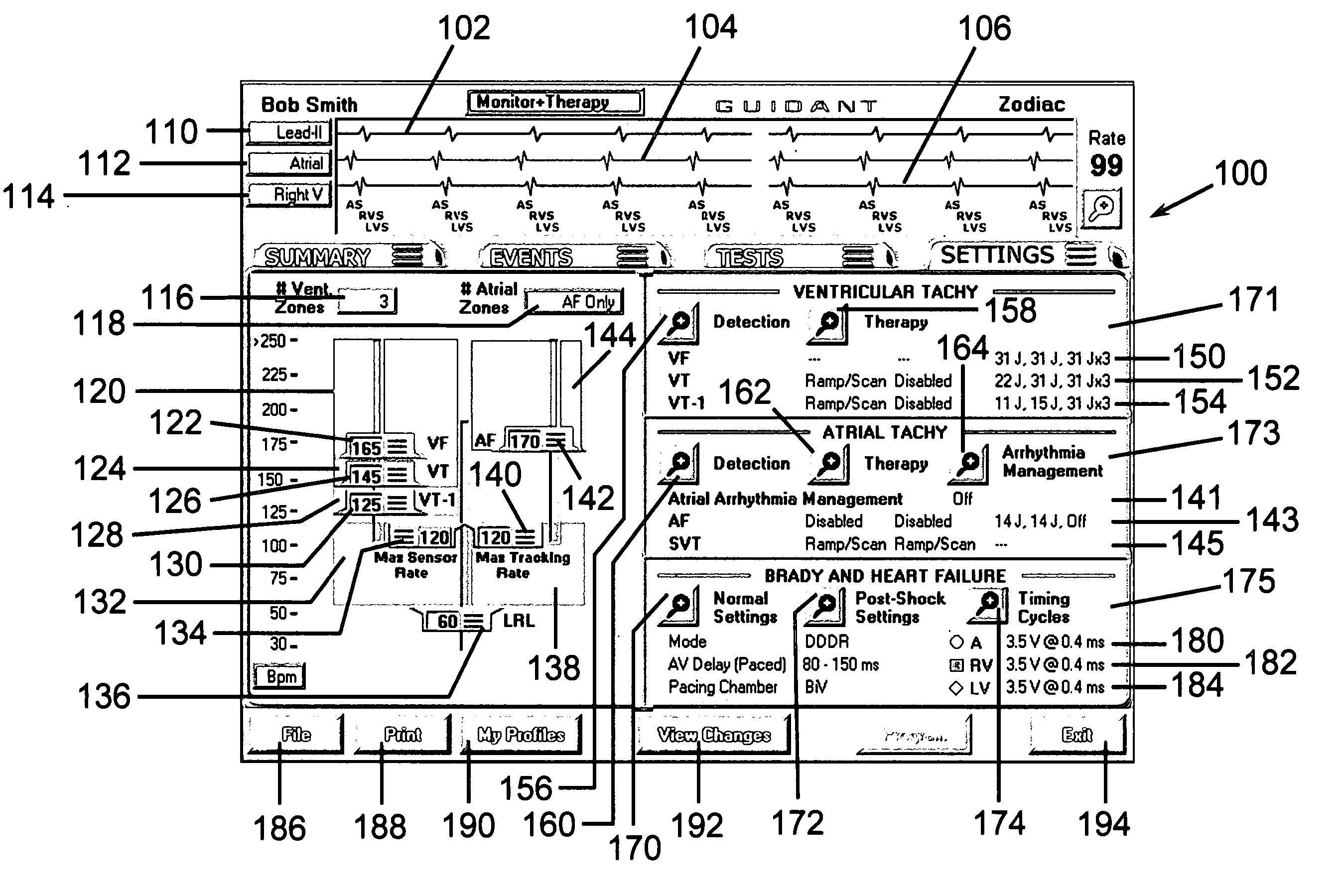
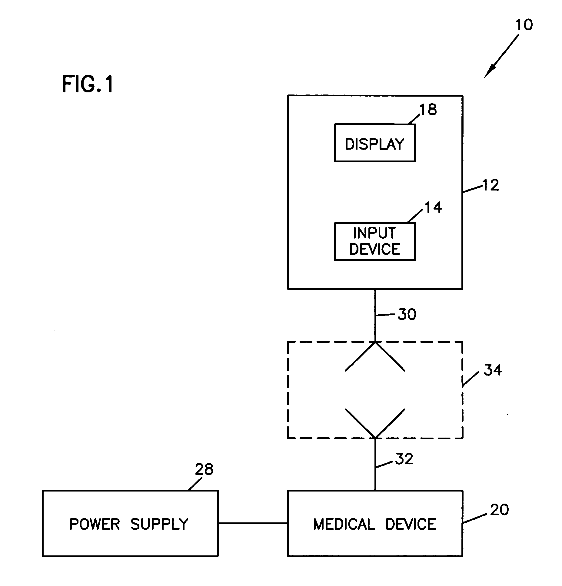
[0011] A medical device system having a medical device and a programming interface, wherein the programming interface provides a method of automatically adjusting parameters to be programmed to a medical device in direct response to a user modifying related parameters that are to be programmed to the medical device. The programming interface is comprised of a graphical user interface including slide controllers that are engaged on the display screen by the system user to graphically modify related parameters on screen. In response to the on screen parameter changes implemented by the user via slide controller movement, the programmer automatically adjusts related parameters on the display scree...

Problems solved by technology

As ICD feature sets become richer and more complex, ICDs are getting increasingly more complicated to program.
For ICDs it can be very difficult for physicians to deal with non-compatibilities with programming.
Such devices may have many features to program and, when physicians go in to program, there may be some inconsistencies that are not recommended by logic or by concerns for safety of the patient.
In addition, physicians were frustrated by error messages, which note an interaction but did not tell them what to do resolve the problem.

Method used


Image

  • Medical device interface system and method
  • Medical device interface system and method
  • Medical device interface system and method

Examples


Embodiment Construction

[0020] In the following detailed description, reference is made to the accompanying drawings that form a part hereof, and in which is shown by way of illustration specific embodiments or examples. These embodiments may be combined, other embodiments may be utilized, and structural, logical and electrical changes may be made without departing from the spirit and scope of the present invention. The following detailed description is therefore, not to be taken in a limiting sense, and the scope of the present invention is defined by the appended claims and their equivalents.

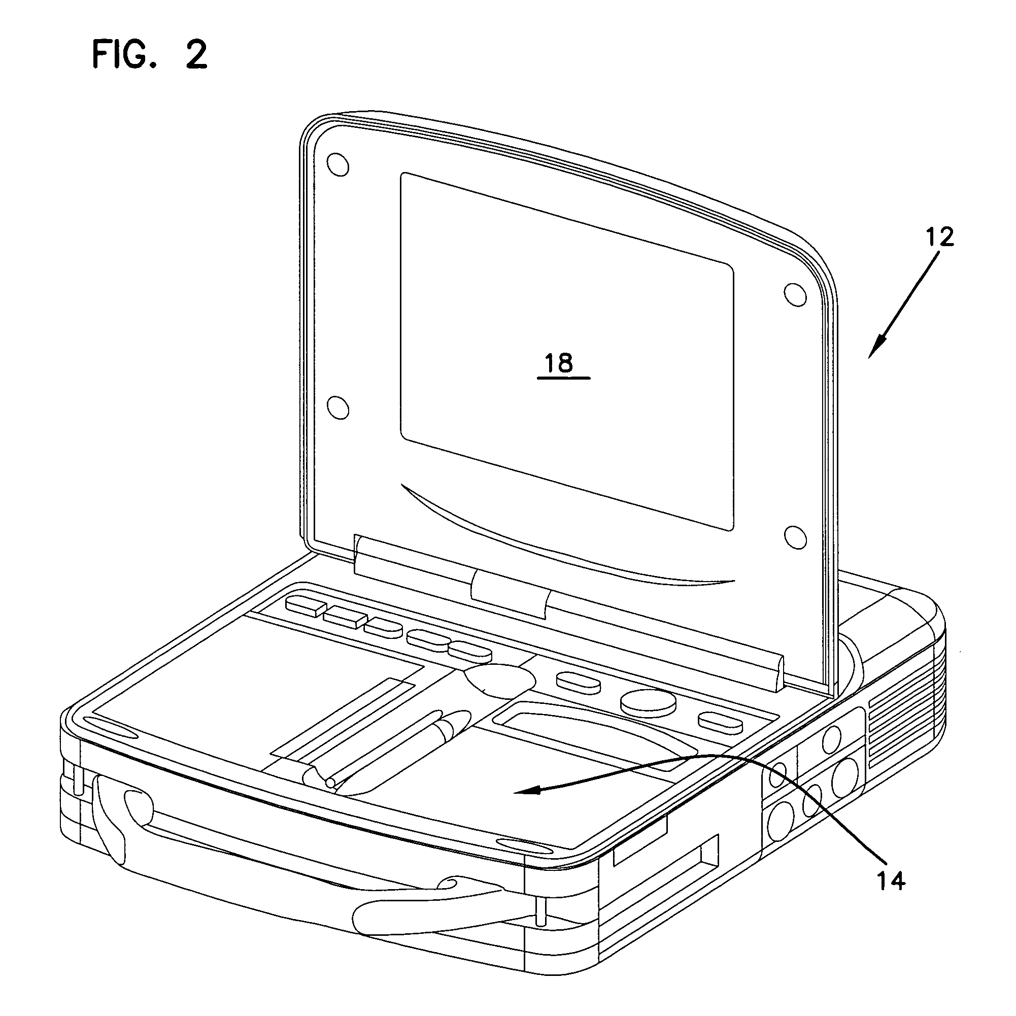
[0021] The present invention is an improved graphical user interface of a programmer used within a medical device system, wherein the medical device system is comprised of a medical device and a medical device programmer. The medical device programmer provides a method for automatically adjusting rate threshold parameters to be programmed to a medical device in direct response to a user modifying related rate thresh...


PUM


Abstract

A medical device programmer graphical user interface, wherein the graphical user interface provides a programmer user with a method of automatically adjusting parameters to be programmed to a medical device in direct response to a user modifying related parameters that are to be programmed to the medical device. The programming interface implements the method in response to the programmer user's use of slide controllers on the programmer display screen to adjust parameters. In response to the on screen parameter changes implemented by the user via slide controller movement, the programmer automatically adjusts related parameters on the display screen by moving slide controllers for related parameters. This automatic adjustment by the programmer graphically illustrates to the user the automatic adjustments being made to the related parameters. The automatic adjustment also graphically illustrates the relationship between parameters being adjusted by the programmer user and the related parameters that are automatically adjusted by the programmer. In response to on screen parameter changes, the system graphically illustrates the parameter values that are changed and those that are programmed to the medical device and those that would cause unsafe condition in the medical device if programmed. The method also prevents the programming to the medical device the parameters that would cause an unsafe condition.

Description

RELATED APPLICATION [0001] This application claims the benefit of provisional application U.S. Ser. No. 60 / 468,946 filed on May 7, 2003, entitled “MEDICAL DEVICE INTERFACE SYSTEM AND METHOD”, Peterson et al.FIELD OF INVENTION [0002] The present invention relates to programming devices used to program implantable programmable medical devices, such as cardioverter-defibrillators and pacemakers. More particularly, but not by way of limitation, the present invention relates to improvements in the graphical user interface of the programmer devices, wherein the graphical user interface automatically communicates to the programming device user in real-time suggested changes in parameters in response to the user's modification of related parameters. The programming device graphical user interface improvements also include a method of preventing parameter modification that creates unsafe conditions. BACKGROUND OF THE INVENTION [0003] Implantable cardiac rhythm CRM devices, more specifically,...

Claims


Application Information

Patent Timeline
IPC IPC(8): A61N1/372A61N1/39
CPCA61N1/3993A61N1/37247Y10S128/903
Inventor PETERSON, LES NORMANDIETERLE, PAULALINDH, PARKALGREN, JAMESGILKERSON, JAMES O.NAUMAN, DOROTHY MARIEPERSEN, KENNETH H.SCHWARTZ, MARK JOSEPHKOSHIOL, ALLAN T.BYNUM, TALA L.CALLAHAN, DAVID
Owner CARDIAC PACEMAKERS INC
Learn More