
Apparatus and method for direct measurement of channel state for coded orthogonal frequency division multiplexing receiver

Inactive Publication Date: 2005-01-13
SAMSUNG ELECTRONICS CO LTD
View PDF6 Cites 157 Cited by
  • Summary
  • Abstract
  • Description
  • Claims
  • Application Information

AI Technical Summary

Benefits of technology

Exemplary embodiments of the present invention provide an apparatus and method for direct measurement of the channel state of an OFDM (Orthogonal Frequency Division Multiplexing) receiver which can increase SNR (Signal-to-Noise Ratio) gain by using a squared Euclidean distance between a received signal value and a de-mapped value for measurement of the channel state, is adaptable to a frequency selective channel, can estimate more reliable CSI (Channel State Information) that is suitable for signal processing with co-channel interference, and / or generate CSI that can be used for bit metric calculations of a subsequent error correction decoder, such as a Viterbi decoder.
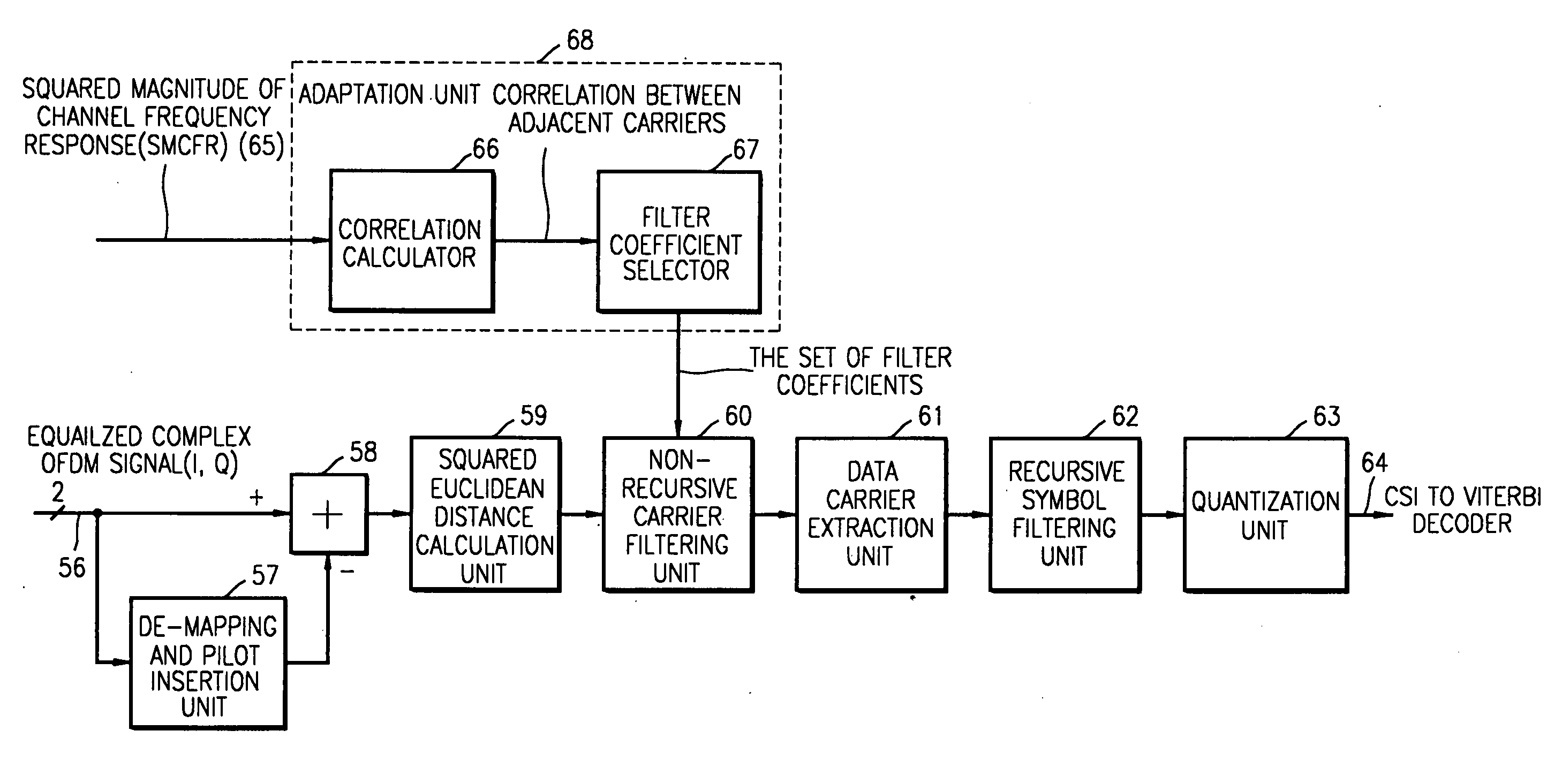
Another exemplary embodiment of the present invention is directed to a method of directly measuring the channel state of an OFDM receiver including estimating a correlation coefficient signal of two or more adjacent carriers using a signal corresponding to an inverse a squared magnitude of the channel frequency response, outputting filtering coefficients belonging to a filtering coefficient group selected according to the estimated correlation coefficient signal, receiving a complex signal for a carrier and calculates a squared value of a signal for I (In-phase) and a squared value of a signal for Q (Quadrature) of the carrier and outputs a first error, which is a sum of the squared values, delaying a first error by one or more carriers and a multiplier unit which multiplies the filtering coefficients by a present carrier value and the one or more delayed carrier values, and outputting a second error which is a sum of the multiplied values, wherein the second error signal is used to improve channel state estimation.

Problems solved by technology

This type of method exhibits good performance in a channel with white noise or in a static channel, but does not exhibit good performance in a channel with channel interference, such as a frequency selective channel or a mobile channel.
Since analog TV signals are mixed with DVB-T (Terrestrial Digital Video Broadcasting) signals and co-channel interference exists in a co-channel, which has a spectrum as shown in FIG. 7, an indirect method of channel state measurement is not suitable for estimating a channel containing analog TV signals mixed with DVB-T signals.
Conventional direct methods exhibit good performance in a channel with channel interference, such as a frequency selective channel or a mobile channel, but do not exhibit good performance in a channel with white noise or in a static channel.
A conventional combined method of channel state measurement discussed in European Pat. No. EP1,221,793, but does not exhibit better performance than a conventional indirect method used for a channel with channel interference, such as a frequency selective channel or a mobile channel.
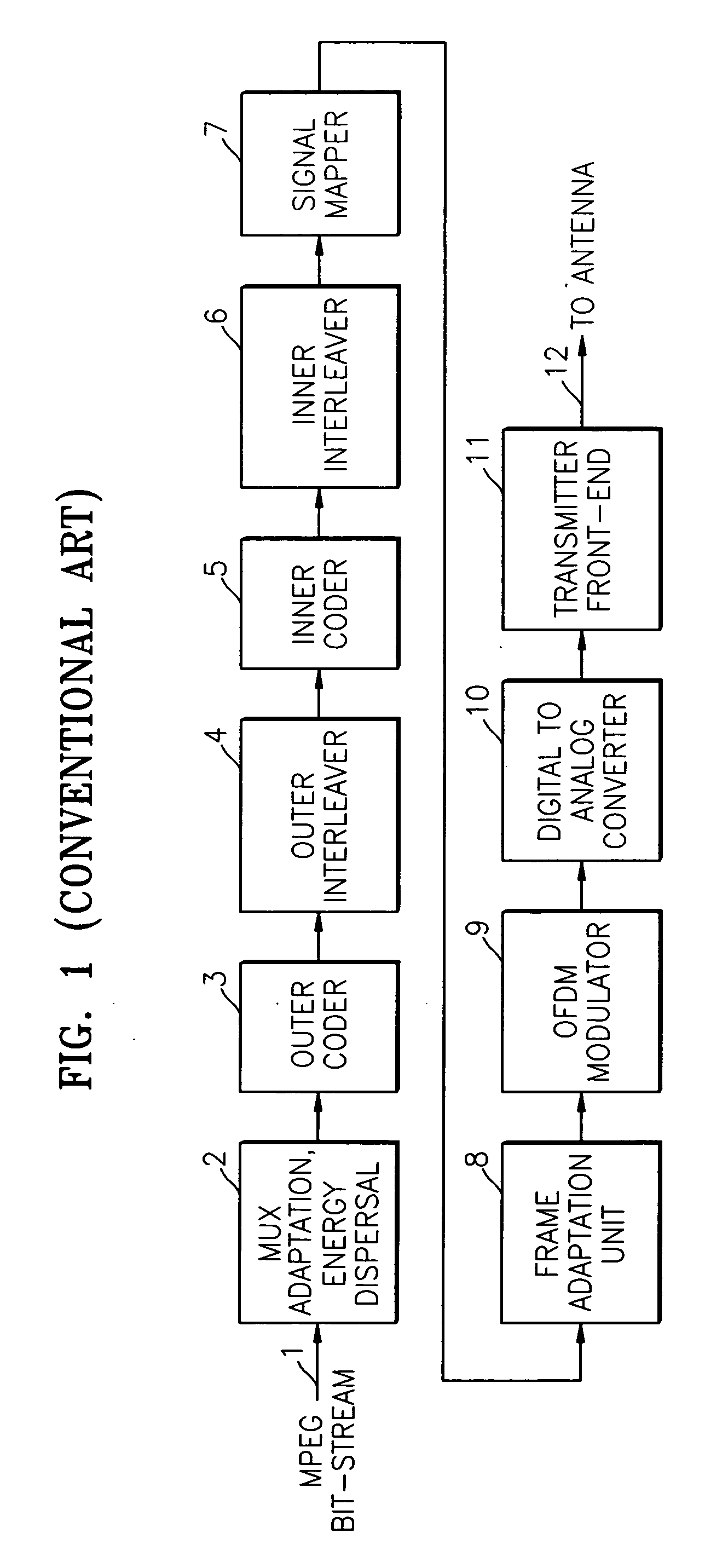
The conventional DVB-T receiver shown in FIG. 3 adopts an indirect measurement of a channel state using SMCFR, and some problems exist, as described above.
However, a problem exists in that this method is suitable for a static channel but not suitable for a dynamic or mobile channel.
For the same reason as shown in FIG. 7, conventional direct methods may not be suitable for DVB-T signal processing with co-channel interference, because a correlation characteristic of each channel is different from each other.
Further, as shown in FIG. 8, another problem exists in that conventional direct methods may not suitable for a frequency selective channel (for example, 2K mode, 8K mode, 16K mode, or 32K mode, etc.).

Method used


Image

  • Apparatus and method for direct measurement of channel state for coded orthogonal frequency division multiplexing receiver
  • Apparatus and method for direct measurement of channel state for coded orthogonal frequency division multiplexing receiver
  • Apparatus and method for direct measurement of channel state for coded orthogonal frequency division multiplexing receiver

Examples


Embodiment Construction

FIG. 9 is a block diagram of an apparatus for direct measurement of the channel state of an OFDM receiver according to an exemplary embodiment of the present invention. FIG. 10 is a detailed block diagram of FIG. 9 according to another exemplary embodiment of the present invention.

With reference to FIGS. 9 and 10, an apparatus for direct measurement of the channel state of an OFDM receiver according to an exemplary embodiment of the present invention may include a de-mapping and pilot insertion unit 57, a subtraction unit 58, a squared Euclidean distance calculation unit 59, a non-recursive carrier filtering unit 60, a data carrier extraction unit 61, a recursive symbol filtering unit 62, and a quantization unit 63. In addition, the apparatus for direct measurement of the channel state of an OFDM receiver may also include a total delay line 81. Also, the apparatus for direct measurement of the channel state of an OFDM receiver may also include an optional adaptation unit 68.

The d...


PUM


Abstract

An apparatus and method for direct measurement of the channel state of a receiver, such as an OFDM (Orthogonal Frequency Division Multiplexing) receiver. The apparatus adapts a frequency selective channel using a squared Euclidean distance between a received signal value and a de-mapped value for measurement of the channel state and estimates the CSI (Channel State Information) which is also suitable for signal processing with co-channel interference. The estimated CSI may be used in a bit metric calculation of subsequent error correction decoders, such as a Viterbi decoder, to increase system SNR (Signal-to-Noise Ratio) gain. Because receiving equipment, such as digital televisions, receive clearer DVB-T (Terrestrial Digital Video Broadcasting) signals, clearer pictures with less distortion can be displayed, for example, on the digital television.

Description

CROSS-REFERENCE TO RELATED APPLICATIONS This application claims the benefit under 35 U.S.C. § 119(a) of Korean Patent Application No. 2003-0046326, filed on Jul. 9, 2003, the contents of which are hereby incorporated by reference in their entirety. BACKGROUND OF THE INVENTION 1. Field of the Invention The present invention relates to an OFDM (Orthogonal Frequency Division Multiplexing) receiver, and more particularly, to an apparatus and method for direct measurement of a channel state using sub-carriers of OFDM signals. 2. Description of the Related Art CSI (Channel State Information) is generally defined by a SNR (Signal-to-Noise Ratio) of a sub-carrier. There are at least three conventional measurement methods for CSI, an indirect measurement method, a direct measurement method, and a combined method. A conventional indirect method of channel state measurement uses the magnitude of a channel frequency response calculated in a channel equalizer. This type of method exhibits ...

Claims


Application Information

Patent Timeline
IPC IPC(8): H04J11/00H04L25/03H04N7/015
CPCH04L25/03184H04L2025/03414H04L25/03292H04N7/015
Inventor ZHIDKOV, SERGEY
Owner SAMSUNG ELECTRONICS CO LTD
Learn More