
Invisable stove top

a stove top and invisibility technology, applied in the field of invisibility stove tops, can solve the problems of inability to use other surface top materials in the current state of the art, discontinuity in the aesthetics of surface top area, etc., to achieve the effect of increasing the versatility and aesthetics of the cook top area, eliminating the disadvantages and weaknesses of the construction, and more versatile cook top area

Inactive Publication Date: 2005-01-13
SULLIVAN STEVEN LEO
View PDF8 Cites 21 Cited by
  • Summary
  • Abstract
  • Description
  • Claims
  • Application Information

AI Technical Summary

Benefits of technology

[0004] The object of the invention is to properly arrange a cooking area and exactly position that area where desired, thus increasing the versatility and aesthetics of the cook top area. The placement of the induction heating element or elements under a granite surface or other suitable decorative surface top material substantially eliminates the disadvantages and weaknesses of the constructs and embodiments of other cook tops and provides for a more aesthetically pleasing installation with the added benefit of a more versatile cook top area.
[0005] Another object is to provide a means of maintaining a much cooler surface top area where the induction elements are active by means of using an insulator in said active area to greatly reduce the amount of heat that is propagated from the cookware used into the surface area below and surrounding said cookware.
[0008] As a result of this arrangement claimed it becomes possible to substantially eliminate the cutting needed to install drop-in inductive heating elements but which does not preclude such cutting for inserting decorative Granite with differing colors and / or materials which mayor may not be flush with the surrounding surface area.
[0009] The method of positioning the identifying cook top area and attaching the induction coils to the under side of the counter top may be accomplished in several ways a few of which will be described. The most effective means of determining the exact position that needs to be identified as the cook top element area is by using flux paper or other visual aid which will identify the exact position of the active magnetic flux field areas thus allowing for exact placement of the markings and / or material or projected light for identifying the stove top elements.

Problems solved by technology

This creates a discontinuity in the aesthetics of surface top area.
There is a lacking in the current state of the art in the use of other surface top materials, which are stable and / or resistant to the presence of high heat from cookware with induction type of heating elements, which would include the use of heat resistant materials such as Stone, Slate, Granite, Silestone, Zodiac and / or other suitable materials in the area of cook top design.

Method used


Image

  • Invisable stove top
  • Invisable stove top

Examples


Embodiment Construction

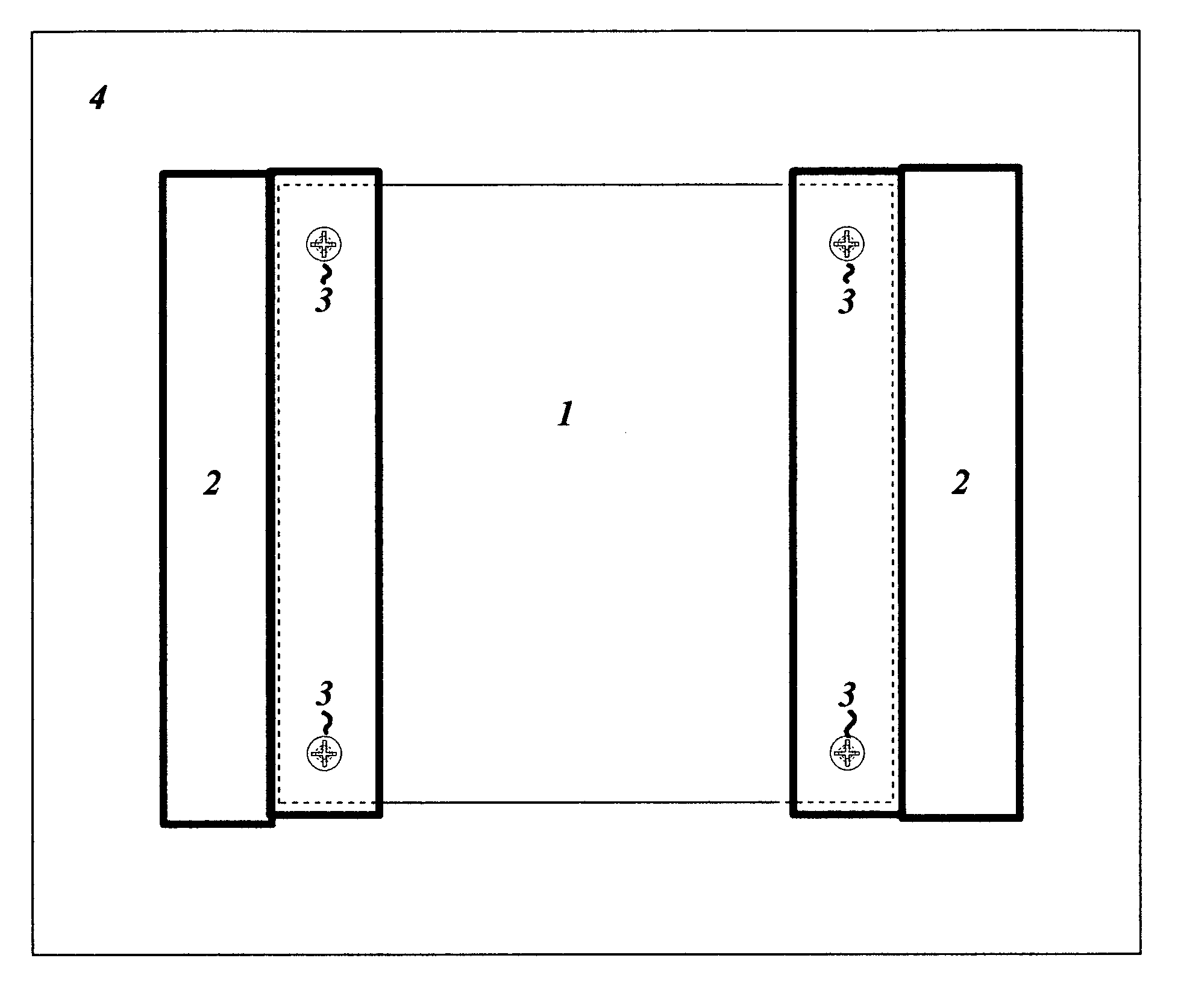
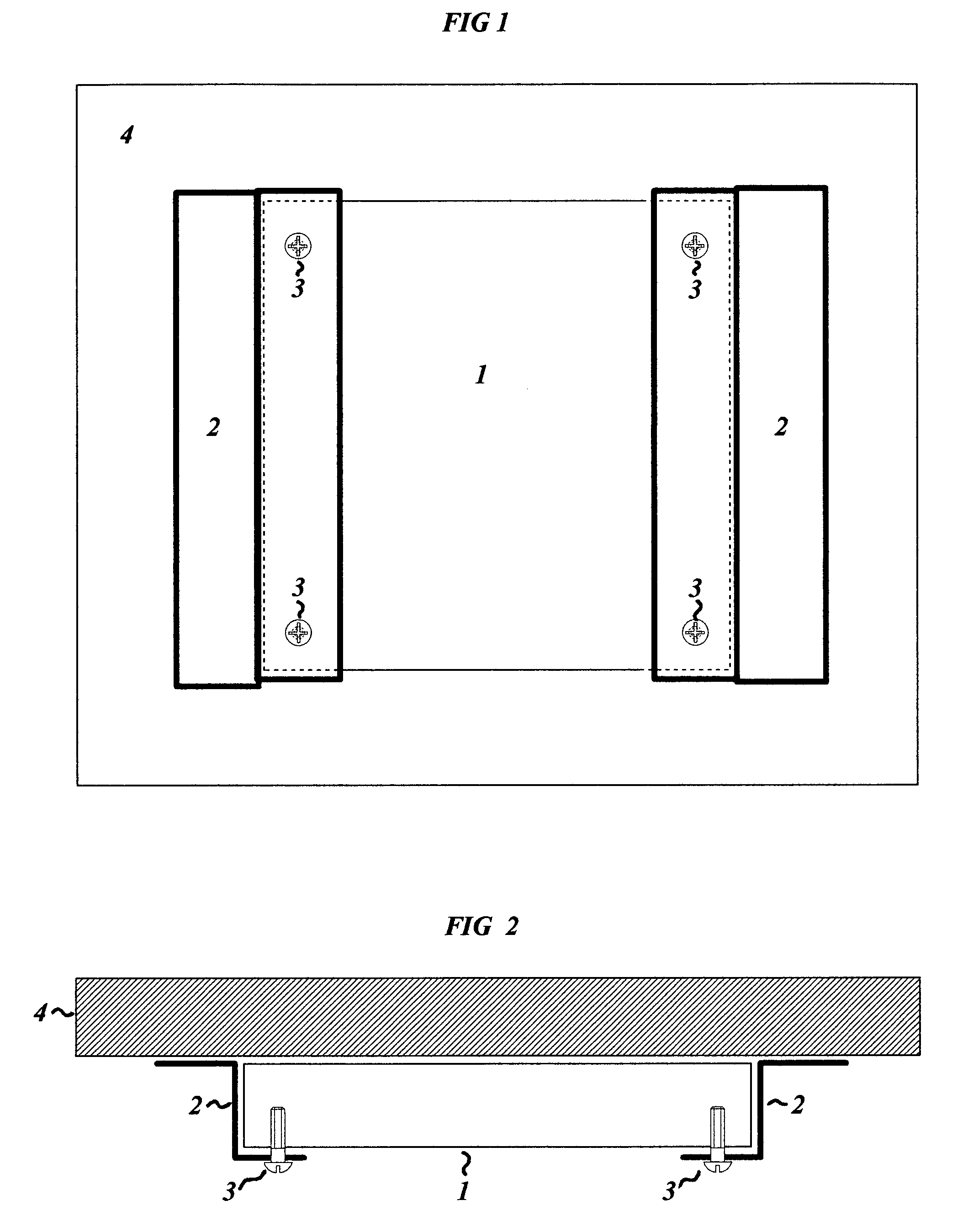
[0015]FIG. 1 shows a bottom up view of an arrangement of one inductive heating element placed under a granite counter top surface.

[0016]FIG. 2 shows a side view of FIG. 1.

[0017]4 is the granite counter top or other suitable surface and 1 is the induction heating element with 2 being the support members which holds the weight of the induction element which is attached to the granite surface by means of an adhesive material not shown with mounting screws 3 used to physically secure the induction heating element to the support members 2.

[0018] The details in the patents, patent applications and publications may be considered to be incorporable, at applicant's option, into the claims during prosecution as further limitations in the claims to patentability distinguished from any amended claims from any prior art.

[0019] Although only a few exemplary embodiments of this invention have been described it in no way limits the scope within this invention, those skilled in the art will read...


PUM


Abstract

The present invention relates to a unique arrangement of induction heating elements with surface top materials creating an aesthetically pleasing cook top area. More specifically it relates to the integration of electric induction coils with a decorative high heat surface top such as granite, slate, concrete, Silestone, Zodiac or other suitable decorative surface and a method for properly identifying the cook top area.

Description

FIELD OF THE INVENTION [0001] The present invention relates to the integration of an electric induction coil with a suitable surface top material such as to produce a continuous and / or seamless flat top surface, which would be deemed aesthetically pleasing to the eye. BACKGROUND OF THE INVENTION [0002] Previously developed induction cook tops use a cook top material such as ceramic and / or glass surface top material. This creates a discontinuity in the aesthetics of surface top area. The advantage of using such a new integration method would be that there would be no need for discontinuity of the top surface aesthetics with the added benefit of a continuous and / or seamless flat top surface with the cook top being invisible; except for the markings and / or material or lighting that would be provided in order to identify the cooking area. [0003] There is no need for heat-permeable material or a thermally conductive surface top material when using induction type of heating elements. The ...

Claims


Application Information

Patent Timeline
Patent Type & Authority Applications(United States)
IPC IPC(8): H05B6/12
CPCH05B6/1209
Inventor SULLIVAN, STEVEN LEO
Owner SULLIVAN STEVEN LEO
Learn More