
System for controlling the combustion noise a motor vehicle diesel engine

a technology for diesel engines and combustion noise, which is applied in the direction of electric control, machines/engines, mechanical equipment, etc., can solve the problems of dispersion of engine characteristics, drifting over time in the delivery characteristics, and the injection system of diesel engines, so as to reduce the operating noise of the engine

Inactive Publication Date: 2005-01-13
PEZHO SITROEN AUTOMOBILS SA +1
View PDF1 Cites 26 Cited by
  • Summary
  • Abstract
  • Description
  • Claims
  • Application Information

AI Technical Summary

Benefits of technology

The object of the present invention is to solve the above-mentioned problems by proposing an approach that is not based on a model, and that is effective in minimizing combustion noise, that can be applied simply and at very low cost in terms of computation complexity and time.
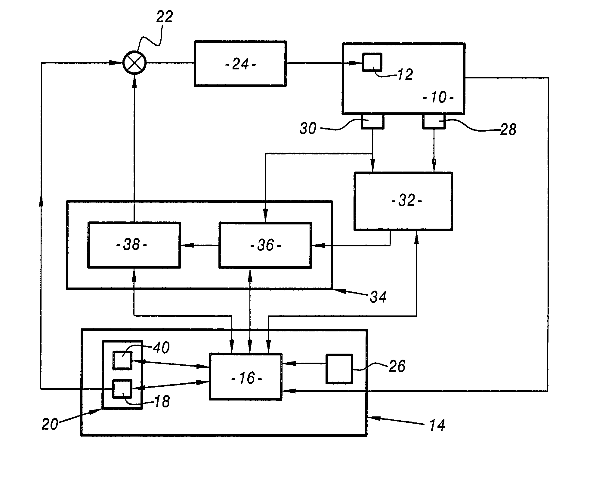
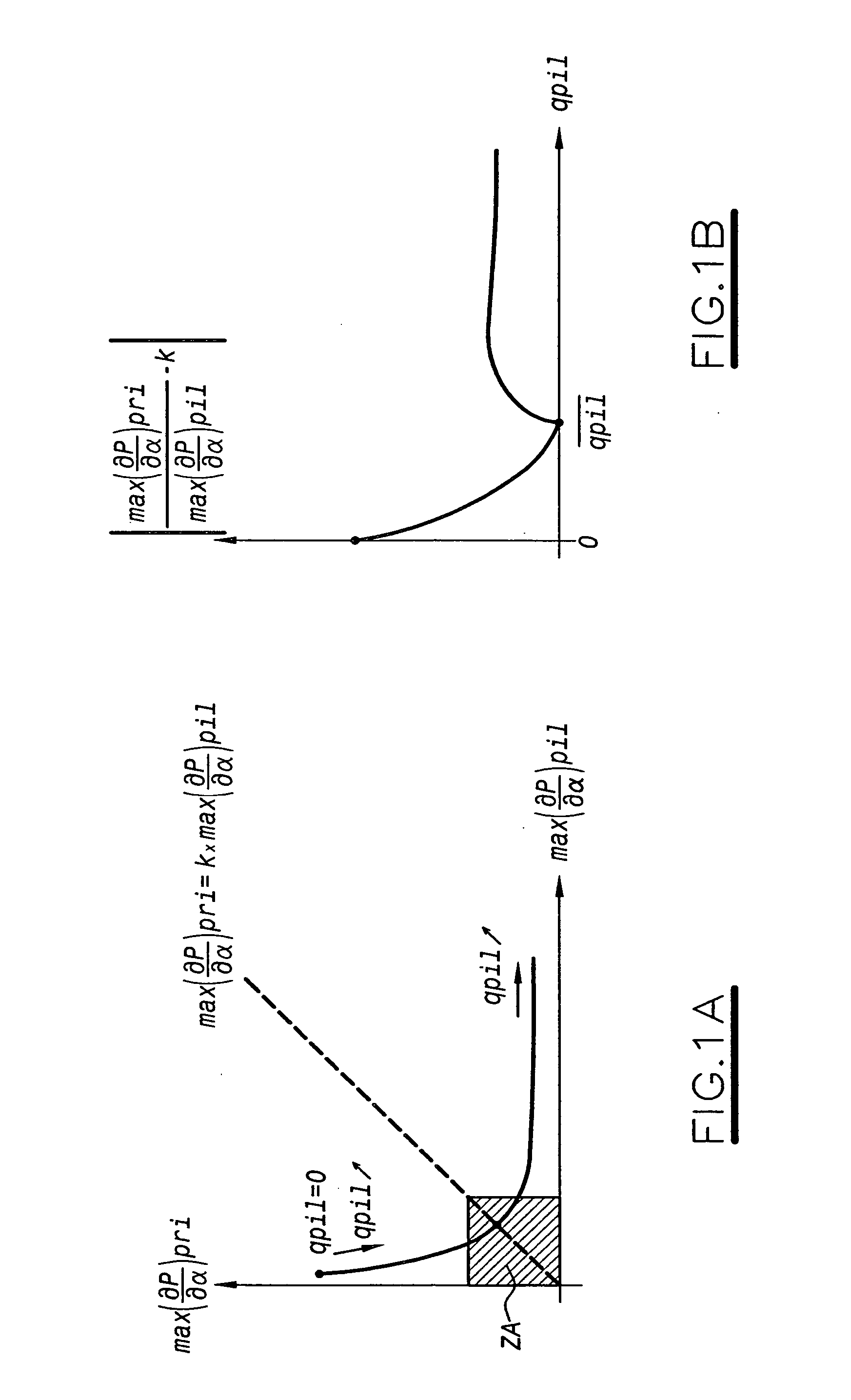
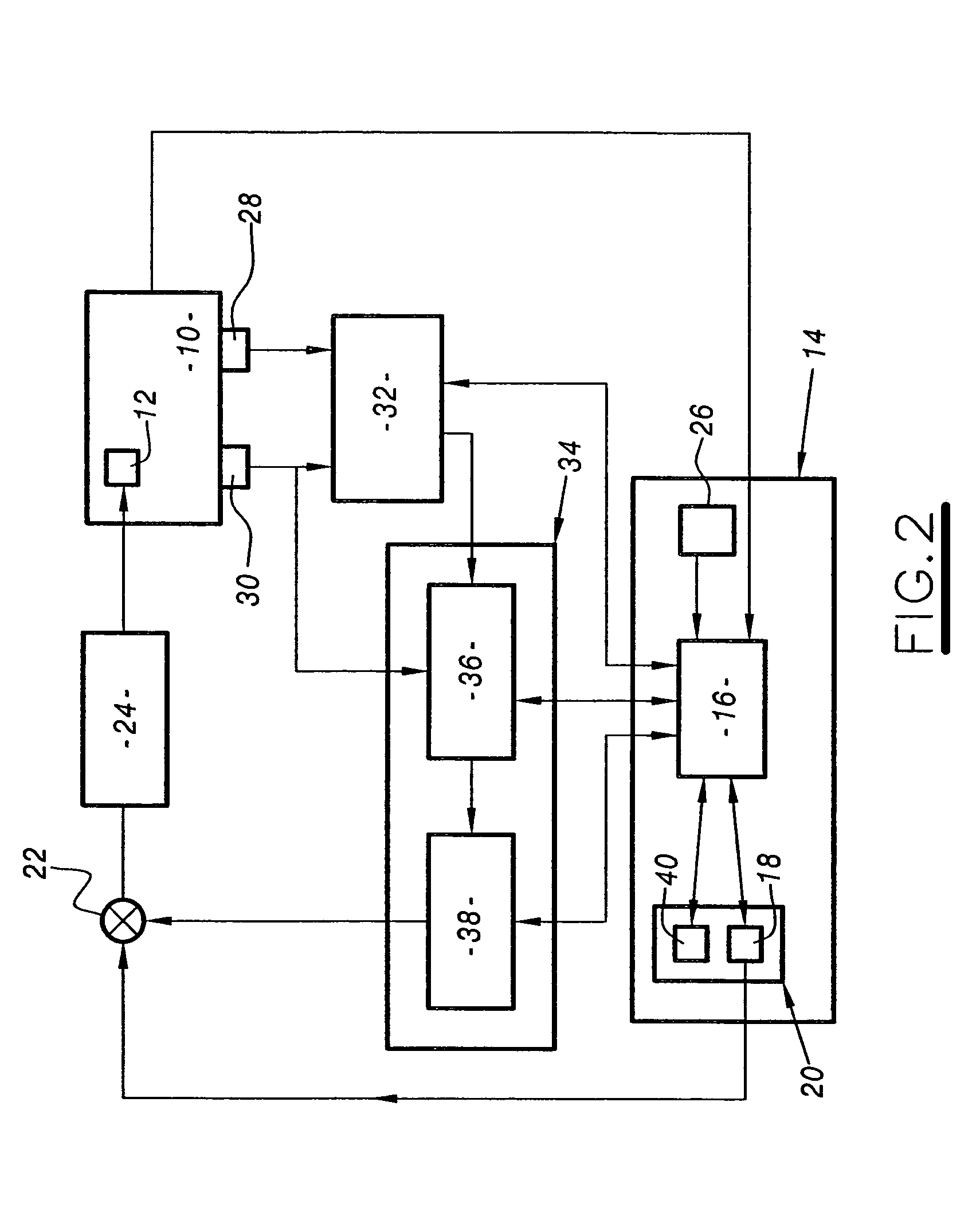
To this end, the invention provides a system for controlling the combustion noise of a motor vehicle diesel engine, the engine being of the type including feeding means for feeding each of its cylinders with multiple injections of fuel, and adapted to trigger fuel feed to each cylinder using at least one pilot injection followed by a main injection of fuel, wherein the system comprises: means for determining pressure gradients in the cylinder of the engine while it is in operation, at least during the pilot and main injection stages; and means for determining the quantity of fuel to be injected into the cylinder during pilot injection for a predetermined quantity of fuel to be injected during main injection so as to optimize an operating criterion of the cylinder based on the ratio between the pressure gradients corresponding to the pilot and main injection stages, and thus optimize the operating noise of the engine.
in the cylinder to around a reference value {overscore (k)} so as to minimize operating noise of the engine.

Problems solved by technology

The present defects of this type of injection system for diesel engines lie firstly in a dispersion of engine characteristics on leaving the factory, e.g. due to manufacturing tolerances and to the extremely high pressures of the system, and secondly to drift over time in the delivery characteristics of the injectors, while the vehicle is in use.
The sum of these drifts leads to degradation of the combustion noise of the engine that is perceived directly by the user of the vehicle.
Nevertheless, such systems present several drawbacks since noise score calculation makes use of a model of the engine and a model of the human ear.
In order to reduce the amplitude of such errors, it becomes necessary to increase the complexity of the model, thereby having the consequence, not only of increasing computation time, but also of increasing the complexity of the system itself, in particular in terms of memory size and computation power of the on-board controller.
In addition, by the very nature of the problem, the engine model used can become obsolete since the characteristics of the engine change over time, implying that the model is no longer representative after a certain length of time, unless its parameters are regularly updated, which likewise involves an increasing degree of complexity.
Furthermore, using a model of the human ear implies the additional disadvantage of assuming that there is only one model that is applicable to the hearing behavior of all users.
That approach requires very long computation time since it makes use of complex digital filtering.
That method does indeed avoid using a model of the human ear, and it does not make direct use of an engine model when calculating the noise score.
However, that method remains difficult to apply in simple manner.
That approach remains an approach that is based on a mathematical model of the engine, if only for the purpose of selecting the basis functions to use, and it is consequently subject to the same drawbacks as are associated with using a model.
Finally, that approach remains expensive in computation time since it requires several successive digital filtering operations in order to obtain information that is useful for controlling injection.

Method used


Image

  • System for controlling the combustion noise a motor vehicle diesel engine
  • System for controlling the combustion noise a motor vehicle diesel engine
  • System for controlling the combustion noise a motor vehicle diesel engine

Examples


Embodiment Construction

As mentioned above, the amplitude of the combustion noise of an engine, and in particular a motor vehicle diesel engine, depends on the amplitude of the pressure gradient in the combustion chambers of the cylinder during ignition of the fuel. The pressure gradient amplitude is itself directly dependent on the initial conditions of ignition. For an engine fed with fuel that is injected in the form of at least one pilot injection and a main injection, the pilot injection enables favorable conditions to be prepared for the main combustion. Consequently, the less the combustion chamber has been prepared by a pilot injection at the beginning of ignition of the main quantity of fuel, the more sudden the increase in pressure due to said injection, and consequently the greater the amount of noise generated by the main combustion.

That is why, combustion noise depends not only on pressure gradient during the pilot injection stage, but also on pressure gradient during the main injection sta...


PUM


Abstract

This system for controlling the combustion noise of a motor vehicle diesel engine of the type including means for feeding each of its cylinders with fuel by multiple injections of fuel, which means are adapted to trigger fuel feed into each cylinder in the form of at least one pilot injection and a main injection of fuel, comprises: means for determining pressure gradients in the engine cylinder while in operation, at least during the pilot and main injection stages; and means for determining the quantity of fuel to be injected into the cylinder during pilot injection for a predetermined quantity of fuel injected during main injection so as to optimize a criterion based on the ratio between the pressure gradients corresponding to the pilot and main injection stages, thereby optimizing the operating noise of the engine.

Description

TECHNICAL FIELD OF THE INVENTION The present invention relates to a system for controlling the combustion noise of a motor vehicle diesel engine. More particularly, the system relates to optimizing the injection setpoint for a diesel engine that includes means, e.g. a common delivery pipe, for feeding fuel to the engine in the form of multiple injections of fuel into each cylinder thereof in order to minimize the combustion noise. BACKGROUND OF THE INVENTION The present defects of this type of injection system for diesel engines lie firstly in a dispersion of engine characteristics on leaving the factory, e.g. due to manufacturing tolerances and to the extremely high pressures of the system, and secondly to drift over time in the delivery characteristics of the injectors, while the vehicle is in use. Furthermore, over its lifetime, the engine's own characteristics vary, for example the compression ratio in the cylinders, and the permeability of the valves or of the piston rings, ...

Claims


Application Information

Patent Timeline
IPC IPC(8): F02D35/02F02D41/14F02D41/38F02D41/40
CPCF02D41/1497F02D41/3827F02D41/403F02D2200/025Y02T10/44F02D35/023F02D2041/1432
Inventor VERMONET, CLAIREMEISSONNIER, GUILLAUMELORRET, CEDRICBAUGE, YVON
Owner PEZHO SITROEN AUTOMOBILS SA
Learn More