Ultrasonic scatterer, ultrasonic imaging method and ultrasonic imaging apparatus

Inactive Publication Date: 2005-01-06
FUJIFILM CORP
View PDF13 Cites 11 Cited by
  • Summary
  • Abstract
  • Description
  • Claims
  • Application Information

AI Technical Summary

Benefits of technology

The another object of the invention is to provide an ultrasonic imaging method and an ultrasonic imaging apparatus in which a probability of the generation of a sub-harmonic component in the transmission of an ultrasonic wave is high and a sub-harmonic component included in an ultrasonic echo is detected at a speed close to a real time so that an image having an excellent space resolution can be obtained.
According to the structure described above, the ultrasonic wave continuing for ten cycles or more is transmitted to the subject. Consequently, the chaos oscillation or branch phenomenon of a micro bubble is activated to increase a probability of the generation of the sub-harmonic component, and the ultrasonic wave continuing for four cycles or more and less than ten cycles is then transmitted to the subject, thereby detecting the sub-harmonic component included in the ultrasonic echo at a speed close to a real time. Consequently, it is possible to obtain an image having an excellent space resolution.

Problems solved by technology

Therefore, it is impossible to singly detect a micro bubble in a blood vessel.
Therefore, the sub-harmonics cannot be detected singly.
According to such a method, however, the micro balloon is broken.
Therefore, it is impossible to continuously observe the micro balloon injected into a subject in a real time.
Therefore, there is a problem in that the space resolution of an obtained ultrasonic image is reduced if an ultrasonic wave continuing for a long period is used.
However, methods for strengthening subharmonic have not yet been found.
That is, the subharmonic echo from the micro bubbles is generated from the chaos of which the optimal region cannot theoretically be explained, and its behavior is more complicated due to formation of the bubble clouds, thus an ultrasonic scatterer capable of generating a strong subharmonic echo not being defined unequivocally.

Method used


Image

  • Ultrasonic scatterer, ultrasonic imaging method and ultrasonic imaging apparatus
  • Ultrasonic scatterer, ultrasonic imaging method and ultrasonic imaging apparatus
  • Ultrasonic scatterer, ultrasonic imaging method and ultrasonic imaging apparatus

Examples


first embodiment

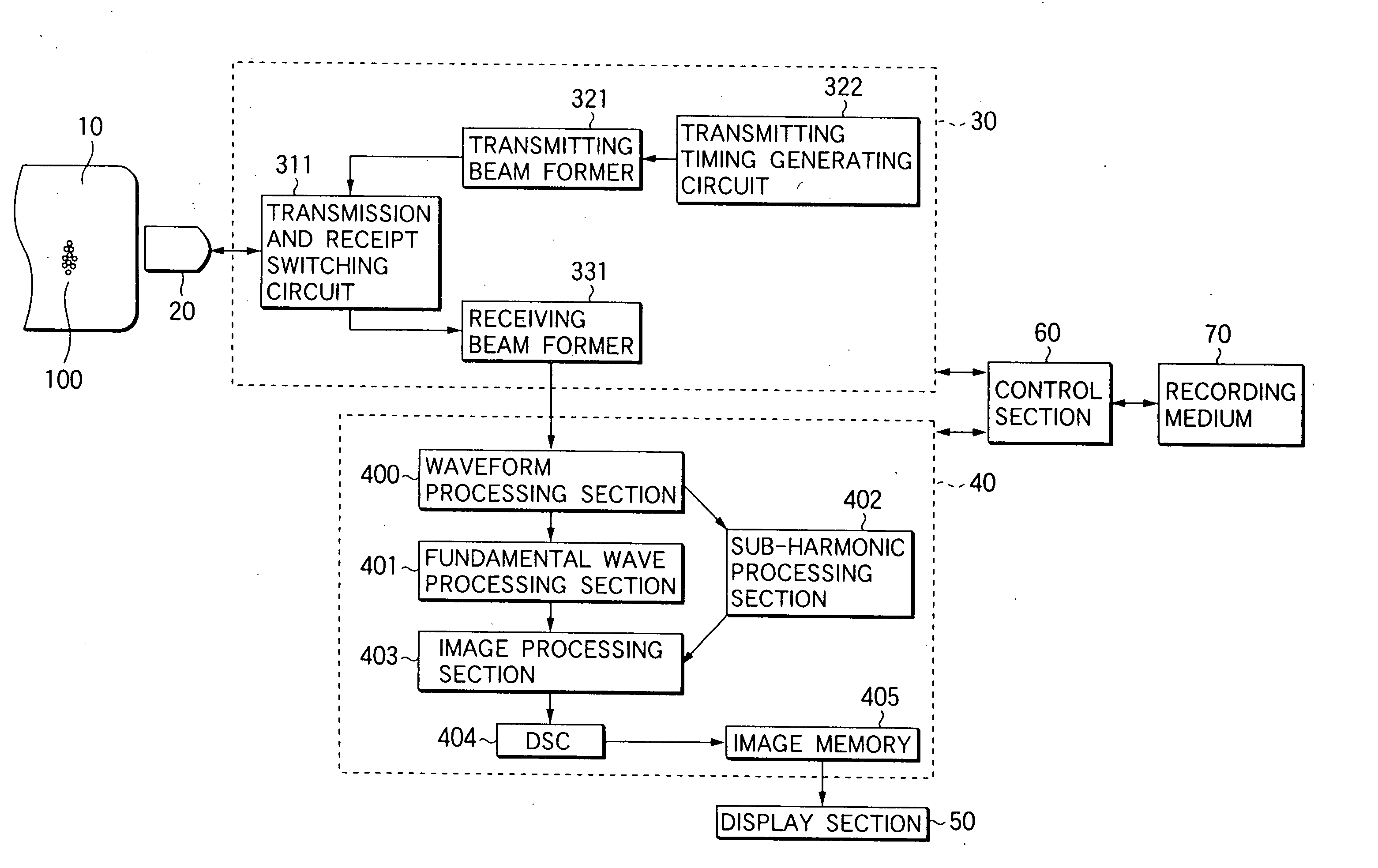
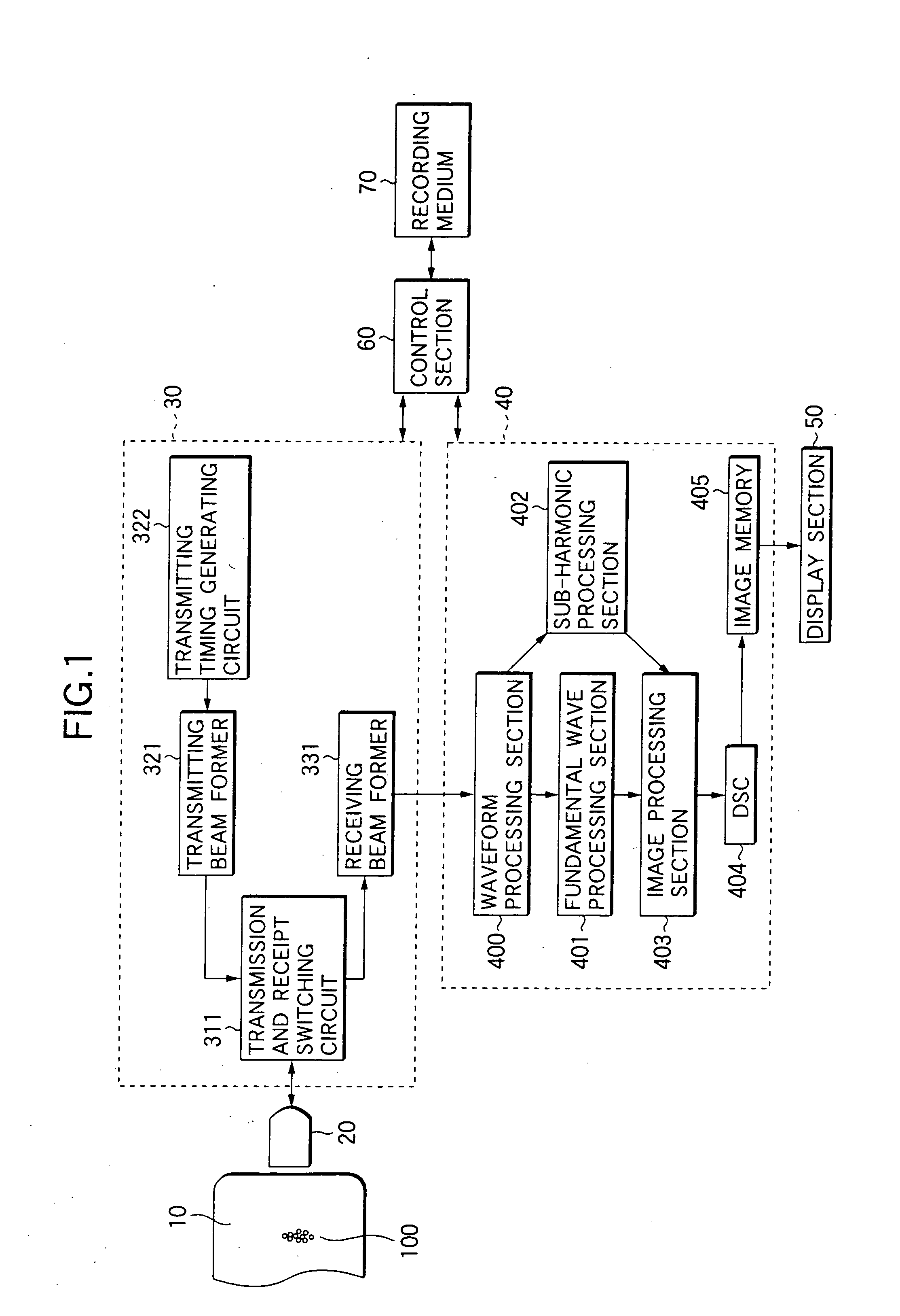
FIG. 1 is a block diagram showing the structure of an ultrasonic imaging apparatus according to the invention.

As shown in FIG. 1, the ultrasonic imaging apparatus comprises an ultrasonic probe 20 including an ultrasonic transducer array constituted by a plurality of ultrasonic transducers. The ultrasonic probe 20 is used in abutment on a subject 10 by an operator. By previous injection of a micro bubble contrast agent, the subject 10 includes a micro bubble 100.

The ultrasonic probe 20 is connected to a transmitting and receiving section 30. In the transmitting and receiving section 30, a transmitting timing generating circuit 322 periodically generates a transmitting timing signal and sends the transmitting timing signal to a transmitting beam former 321. The transmitting beam former 321 generates a plurality of driving signals (transmitting beam forming signals) for driving a plurality of ultrasonic transducers of the ultrasonic probe 20 with a time difference based on the trans...


PUM


Abstract

The ultrasonic scatterer of the invention comprises gas-containing particles having an average particle size of 0.01 μm to 10 μm, the ultrasonic imaging method of the invention comprises transmitting an ultrasonic wave continuing for ten cycles or more; transmitting an ultrasonic wave continuing for four cycles or more and less than ten cycles after a predetermined period passes, and the ultrasonic imaging apparatus of the invention comprises transmitting means for sending a driving signal to the ultrasonic probe so as to transmit, to a subject, an ultrasonic wave continuing for four cycles or more and less than ten cycles after a predetermined period passes subsequently to transmitting, to the subject, of an ultrasonic wave continuing for ten cycles or more.

Description

FIELD OF THE INVENTION The present invention relates to an ultrasonic scatterer, ultrasonic imaging method and ultrasonic imaging apparatus, which highly ensure a generation of sub-harmonic echo. The present invention particularly relates to an ultrasonic scatterer that is useful as a contrast agent for ultrasonic diagnosis, to an ultrasonic imaging method and an ultrasonic imaging apparatus for detecting a sub-harmonic echo intensity by using a micro bubble contrast agent. BACKGROUND OF THE INVENTION In recent years, an ultrasonic diagnosis has been remarkably developed in a diagnosis of breast and abdomen portions because of such a feature that blood flow information can be acquired. In particular, an ultrasonic image pick-up technique using a contrast agent has been developed. Therefore, more accurate blood flow information has been acquired. In such an ultrasonic contrast, a micro bubble contrast agent including a large number of micro bubbles having a diameter of 1 to several...

Claims


Application Information

Patent Timeline
IPC IPC(8): A61B8/00G01N15/00G01N15/02G01S7/52
CPCA61B8/481G01N15/0227G01N15/0272G01S7/52038G01N2015/0088G01S7/52022G01N2015/0046G01N2015/019
Inventor TSUZUKI, HIROHIKO
Owner FUJIFILM CORP
Why Eureka
Try Eureka