
Multiple format radio frequency receiver

a radio frequency receiver and multi-format technology, applied in the field of radio frequency receivers, can solve the problems of delay and additional battery drain, increase design complexity, and inability to optimally configure for both formats

Inactive Publication Date: 2005-01-06
CALIFORNIA EASTERN LAB
View PDF19 Cites 49 Cited by
  • Summary
  • Abstract
  • Description
  • Claims
  • Application Information

AI Technical Summary

Benefits of technology

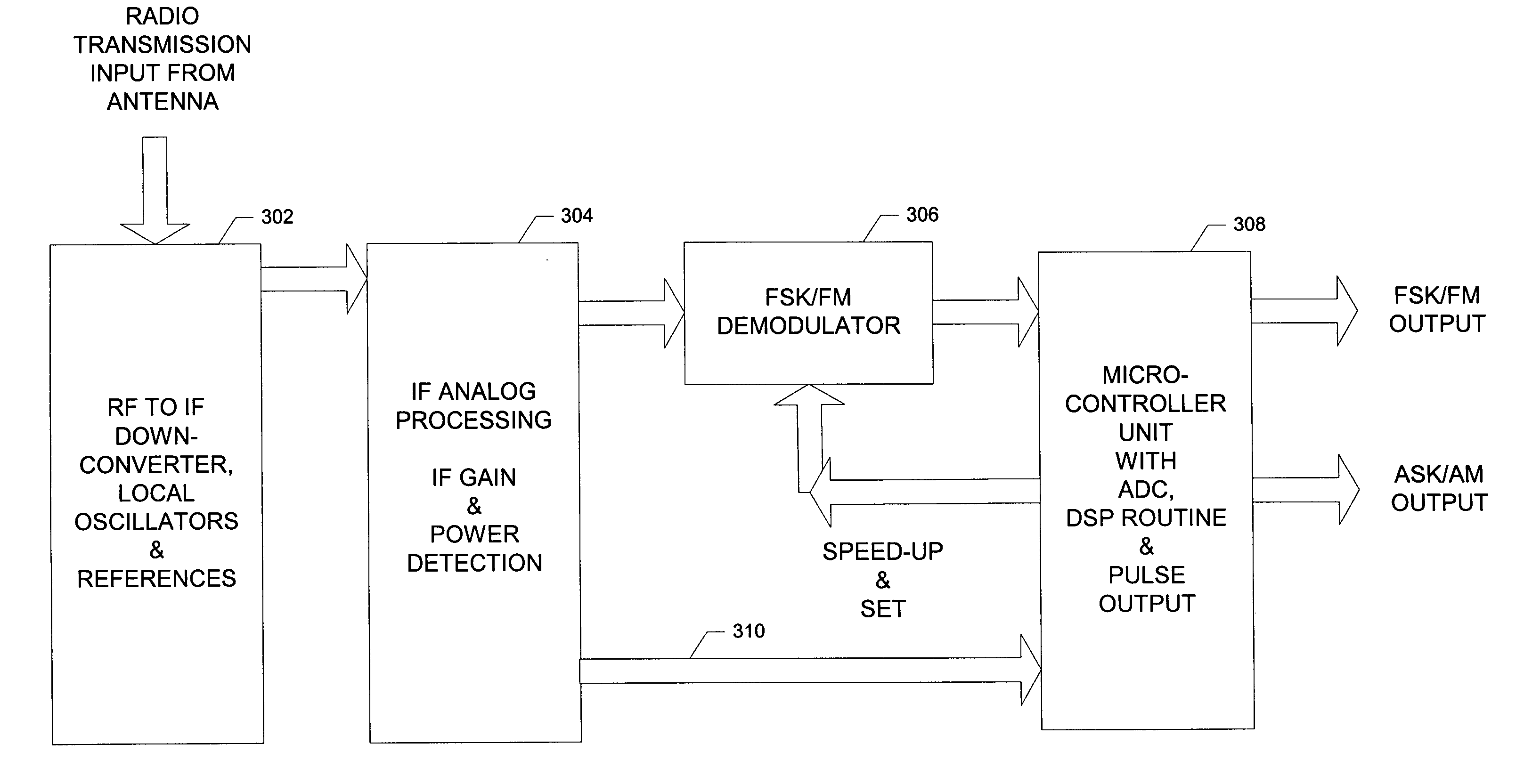
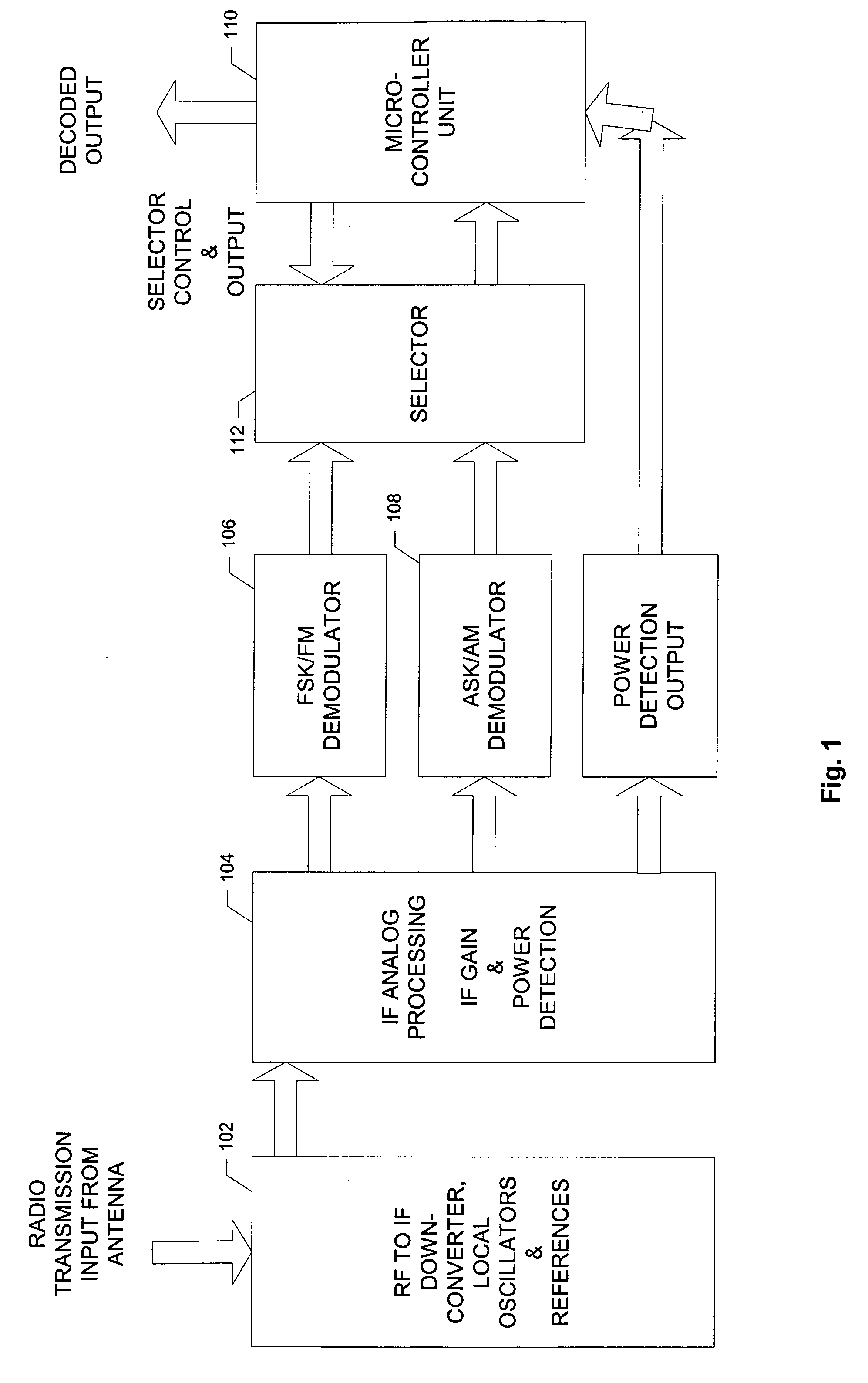
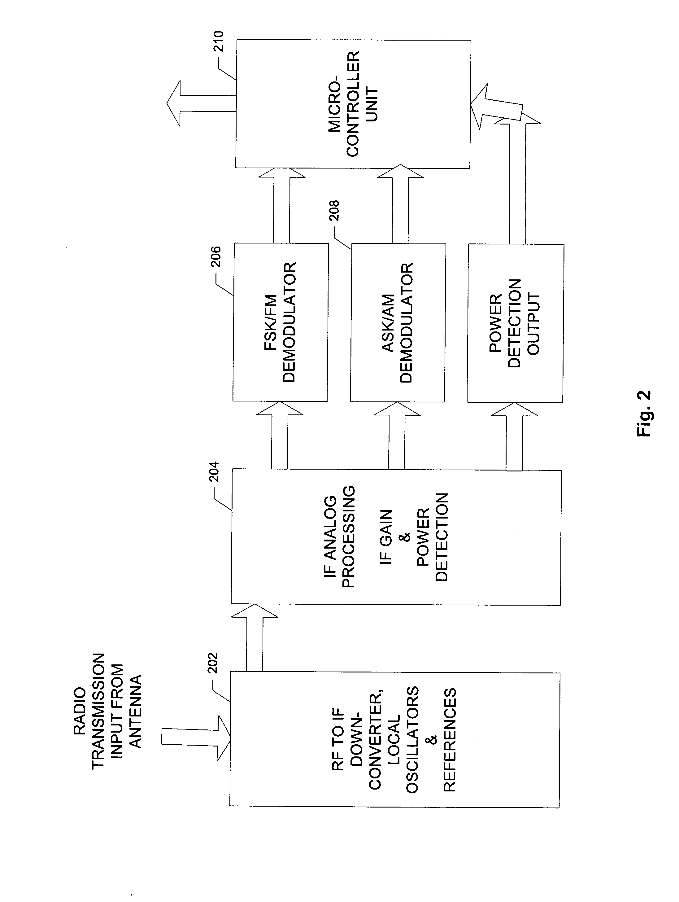
[0012] According to the present invention, RF receivers topologies and systems incorporating such topologies are provided which are operable to receive RF signals using different transmission formats while avoiding some or all of the issues described above. According to a specific embodiment of the invention an RF receiver is provided which includes a down-converter operable to convert a received RF signal to an intermediate frequency (IF) signal. The down-converter is also operable to generate a power detection signal representative of a power level associated with the received RF signal. A hardware demodulator is operable to demodulate the IF signal in accordance with a first modulation format and thereby generate a first demodulated signal. A digital signal processor is operable to process the power detection signal in accordance with a second modulation format and thereby generate a second demodulated signal.

Problems solved by technology

Since the transmitters sending messages to these receivers may not have good timing stability or frequency accuracy, these inaccuracies must be taken into account in the design phase, undesirably increasing design complexity.
In addition to the design complexity and receiver blanking issues described above, these switching and signal acquisition events introduce delays and additional battery drain.
Other compromises in performance may also be associated with the various dual-format receivers on the market.
For example, when a receiver is configured to support two formats, it is often not optimally configured for both of the supported formats at the same time.
It may also not be optimally configured for an individual format when in that particular mode.
Typically the commonality of circuit functions forces compromises in implementation and performance.
Therefore, it is not typically optimized for one format or the other.

Method used


Image

  • Multiple format radio frequency receiver
  • Multiple format radio frequency receiver
  • Multiple format radio frequency receiver

Examples


Embodiment Construction

[0018] Reference will now be made in detail to specific embodiments of the invention including the best modes contemplated by the inventors for carrying out the invention. Examples of these specific embodiments are illustrated in the accompanying drawings. While the invention is described in conjunction with these specific embodiments, it will be understood that it is not intended to limit the invention to the described embodiments. On the contrary, it is intended to cover alternatives, modifications, and equivalents as may be included within the spirit and scope of the invention as defined by the appended claims. In the following description, numerous specific details are set forth in order to provide a thorough understanding of the present invention. The present invention may be practiced without some or all of these specific details. In addition, well known features may not have been described in detail to avoid unnecessarily obscuring the invention.

[0019] According to the prese...


PUM


Abstract

RF receiver topologies and systems incorporating such topologies are described. Various implementations allow the intelligent monitoring of transmission formats, multi-format reception, and real-time receiver parameter optimization.

Description

RELATED APPLICATION DATA [0001] The present application claims priority from U.S. Provisional Patent Application Ser. No. ______ for DUAL MODE FSK / FM & ASK / AM RECEIVER filed Jul. 2, 2003 (Attorney Docket No. CEL1P001P), the entire disclosure of which is incorporated herein by reference for all purposes.BACKGROUND OF THE INVENTION [0002] The present invention relates to radio frequency (RF) receivers and, more specifically, to RF receivers which support multiple radio transmission formats. [0003] Many commercially available RF receivers support reception of only a single transmission format. On the other hand, some specialized receiver chips are required to receive transmissions with different formats within the same radio frequency channel. Some current solutions switch the receiver operational mode between the different formats so only one type of transmission can be received at a time. Many times this involves duplicative circuitry. In addition, such solutions eliminate reception ...

Claims


Application Information

Patent Timeline
Patent Type & Authority Applications(United States)
IPC IPC(8): H04BH04B1/28H04B17/00
CPCH04B1/28
Inventor KUNZ, WILLIAM E.SARKISSIAN, GARO
Owner CALIFORNIA EASTERN LAB
Learn More