
Dispenser activation method and apparatus

a technology of activation method and fuel dispenser, which is applied in the direction of liquid transfer device, packaging goods type, liquid handling, etc., can solve the problems of complex and expensive manufacture, installation and repair, and easy failure of fuel dispensers, and achieve the effect of simplifying the operation of the operator, simplifying the operation and avoiding failur

Inactive Publication Date: 2005-01-06
ENVIRON PROD
View PDF4 Cites 43 Cited by
  • Summary
  • Abstract
  • Description
  • Claims
  • Application Information

AI Technical Summary

Problems solved by technology

Such switches are mechanically activated and, as such, are prone to failure over time after repeated use due to mechanical wear.
In addition, these mechanical switches include numerous components that make them complicated and expensive to manufacture, install and repair.
Further, conventional fuel dispenser designs can be confusing or difficult for an operator to operate because they require the operator to consciously carry out two separate operations before the fueling transaction may begin.

Method used


Image

  • Dispenser activation method and apparatus
  • Dispenser activation method and apparatus
  • Dispenser activation method and apparatus

Examples


Embodiment Construction

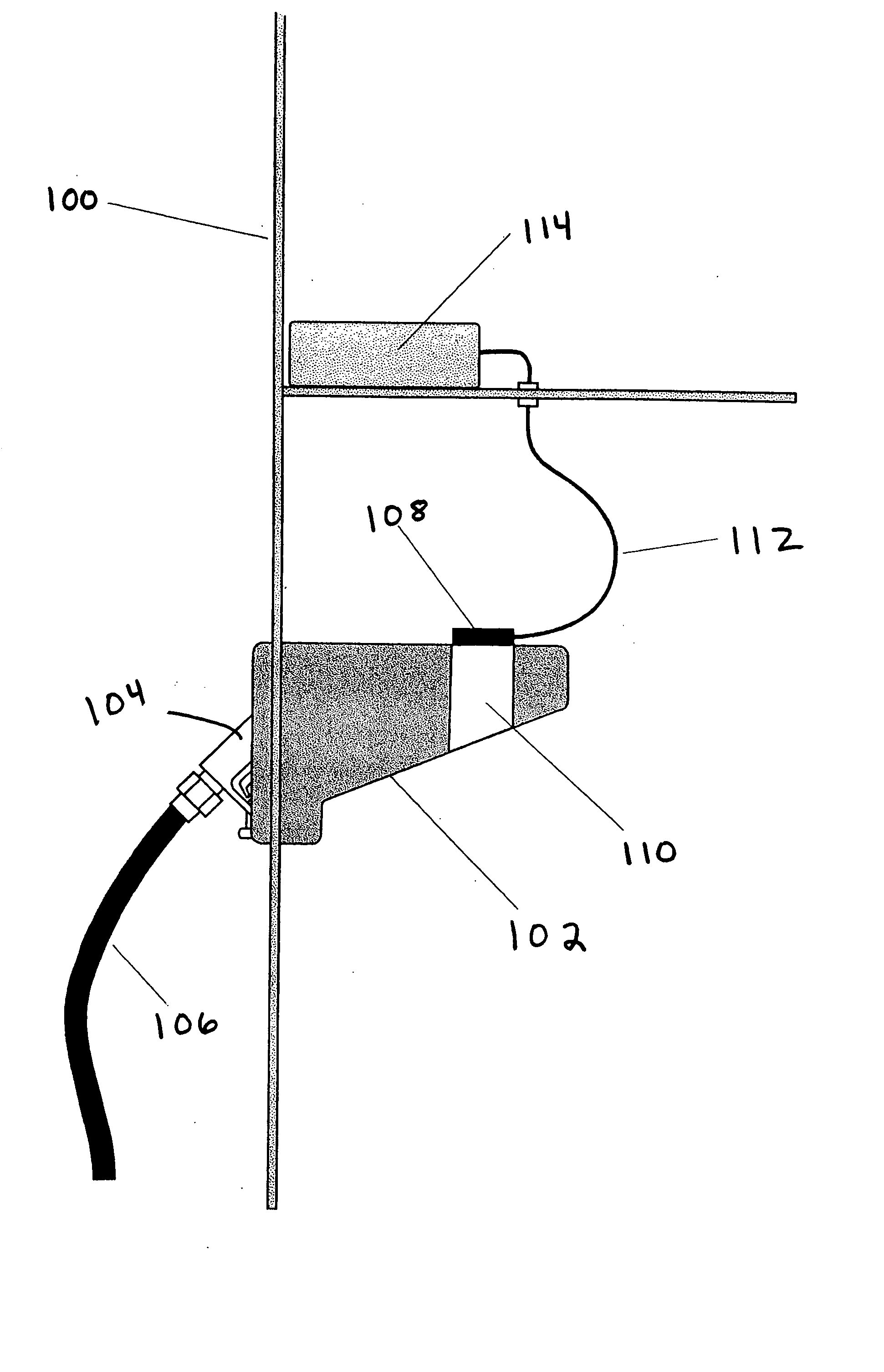
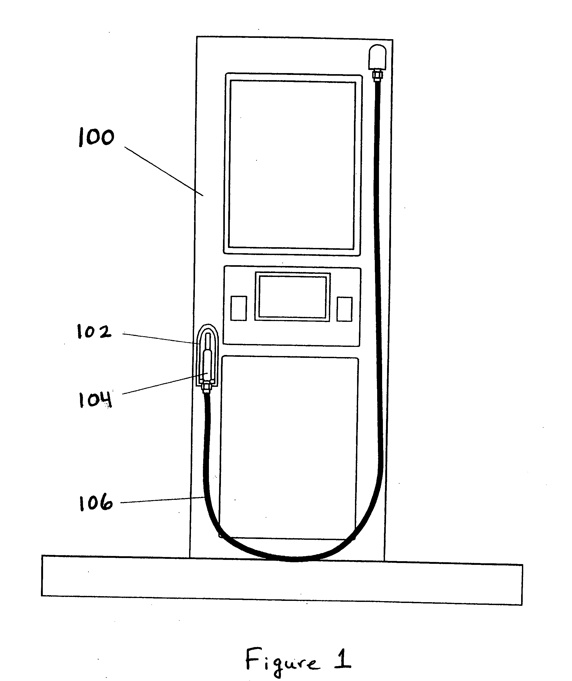
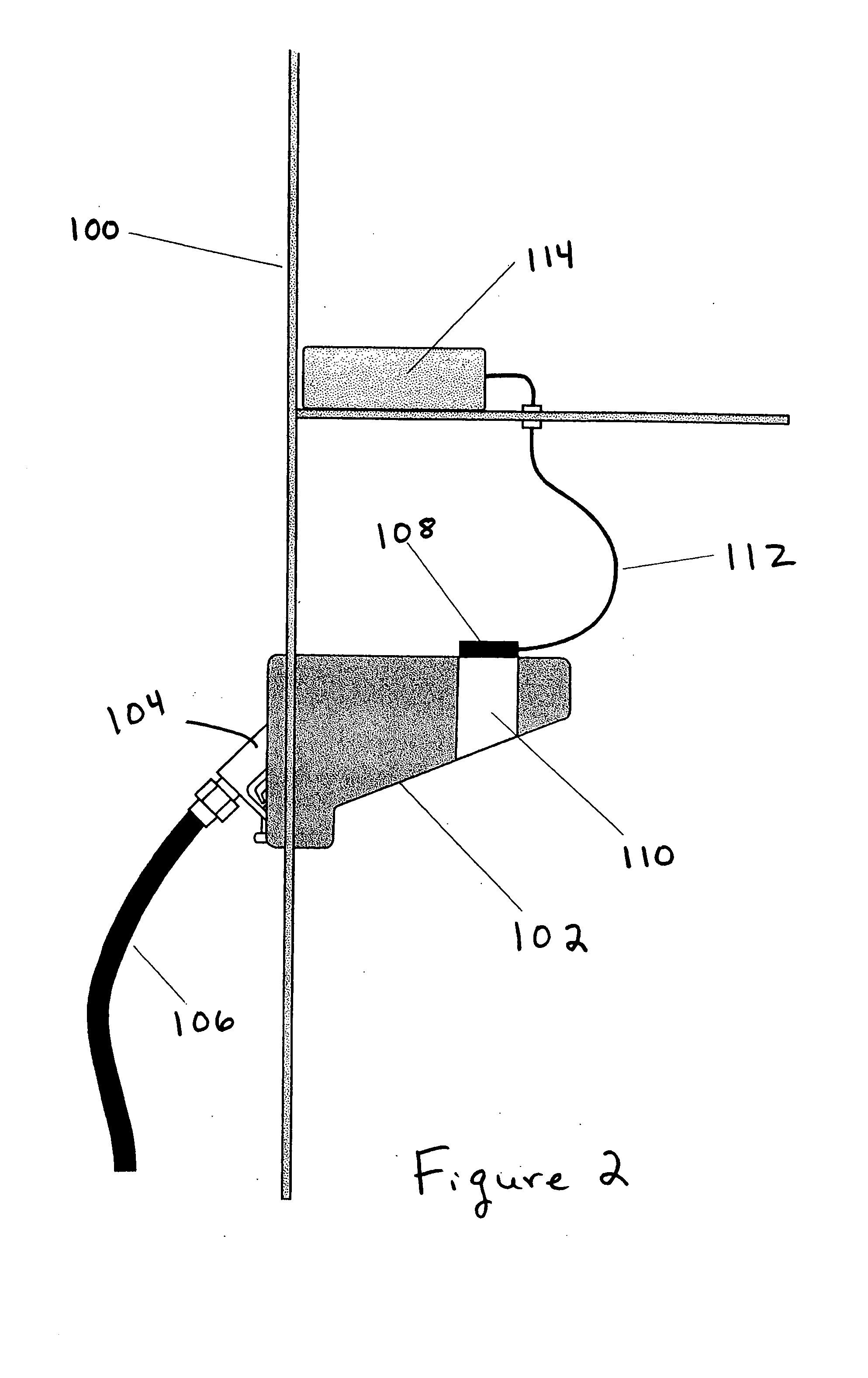
[0019] Referring to the drawings, wherein like reference numerals illustrate corresponding or similar elements throughout the several views, there is shown in FIGS. 1-3 a fuel dispenser 100 according to the present invention. A fueling nozzle 104 is coupled to a fuel source (not shown) via a fueling hose 106. The fueling nozzle 104 may dispense fuel from the fuel source when a fueling transaction is activated and may not dispense fuel when a fueling transaction is terminated.

[0020] The fueling transaction is activated or terminated based on certain factors. Such factors include whether the fueling nozzle 104 is located in or removed from its nozzle boot 102 or holster. When the fueling nozzle 104 is removed from the holster 102, the fuel dispenser 100 may activate the fueling transaction provided that any other requirements or criteria, such as confirmation of payment, are satisfied. When the fueling nozzle 104 is returned to the holster 102, the fuel dispenser 100 terminates the f...


PUM


Abstract

A fuel dispenser includes a non-mechanical switch that detects whether a fueling nozzle is positioned inside or outside of a nozzle boot. When the non-mechanical switch detects that the fueling nozzle is removed from the nozzle boot, the non-mechanical switch generates a signal to activate a fuel dispensing transaction. When the non-mechanical switch detects that the fueling nozzle if replaced in the nozzle boot, the non-mechanical switch generates a signal to terminate the fuel dispensing transaction.

Description

[0001] The invention relates to the field of fuel dispensers. More particularly, the invention is related to detecting the position of a fueling nozzle of a fuel dispenser. This application claims priority from a provisional application, Ser. No. 60 / 456,203, filed Mar. 21, 2003.FIELD OF THE INVENTION BACKGROUND OF THE INVENTION [0002] Most states require that fuel dispensers be configurable to require the operator of the fuel dispenser (i.e., a self-service customer or a service station attendant) to perform at least two operations before allowing a fueling or dispensing transaction to begin. One required operation is for the operator to select the type or grade of fuel. The other required operation is for the operator to actuate a switch to activate the dispensing transaction. With most dispensers, the order or sequence in which these operations are completed is irrelevant. [0003] The selection of a grade of fuel is typically implemented by requiring the operator of the fuel dispen...

Claims


Application Information

Patent Timeline
Patent Type & Authority Applications(United States)
IPC IPC(8): B67D7/04B67D7/12
CPCB67D7/04B67D7/84B67D7/42B67D7/12
Inventor WEBB, MICHAEL C.STRUTHERS, KEVIN
Owner ENVIRON PROD
Learn More