
Dual bridge angular and linear accelerometer

a linear and angular acceleration technology, applied in the field of accelerometers, can solve the problems of difficult and inefficient process, needing a new accelerometer, etc., and achieve the effect of improving reliability, less power, and reliable angular and linear acceleration measurements

Inactive Publication Date: 2005-01-06
THE BOEING CO
View PDF4 Cites 9 Cited by
  • Summary
  • Abstract
  • Description
  • Claims
  • Application Information

AI Technical Summary

Benefits of technology

The present invention is a dual bridge accelerometer system that generates accurate and reliable angular and linear acceleration measurements. It is designed to improve manufacturing costs and reliability, while also being less affected by changes in temperature or temperature gradients. The system includes an inertial platform and two accelerometers that maintain an attitude in response to a platform stabilizing controller signal. The accelerometers generate signals in response to acceleration, which are then averaged to generate a linear acceleration signal. This system provides a dynamic range and granularity sufficient for Inter-Continental Ballistic Missile (ICBM) usage.

Problems solved by technology

This is often a difficult and inefficient process.
The disadvantages associated with current accelerometer systems have made it apparent that a new accelerometer is needed.

Method used


Image

  • Dual bridge angular and linear accelerometer
  • Dual bridge angular and linear accelerometer
  • Dual bridge angular and linear accelerometer

Examples


Embodiment Construction

The present invention is illustrated with respect to an angular and linear accelerometer, particularly suited to the aerospace field. The present invention is, however, applicable to various other uses that may require accelerometers, such as any system requiring position and velocity measurements under extreme conditions, as will be understood by one skilled in the art.

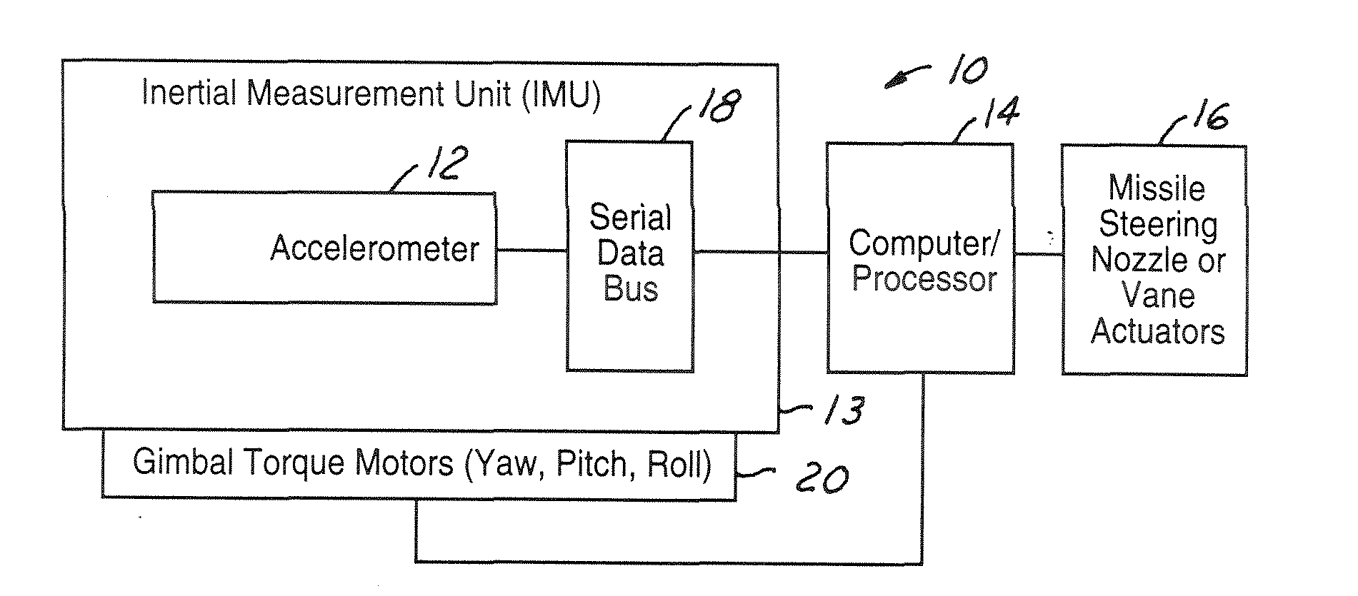
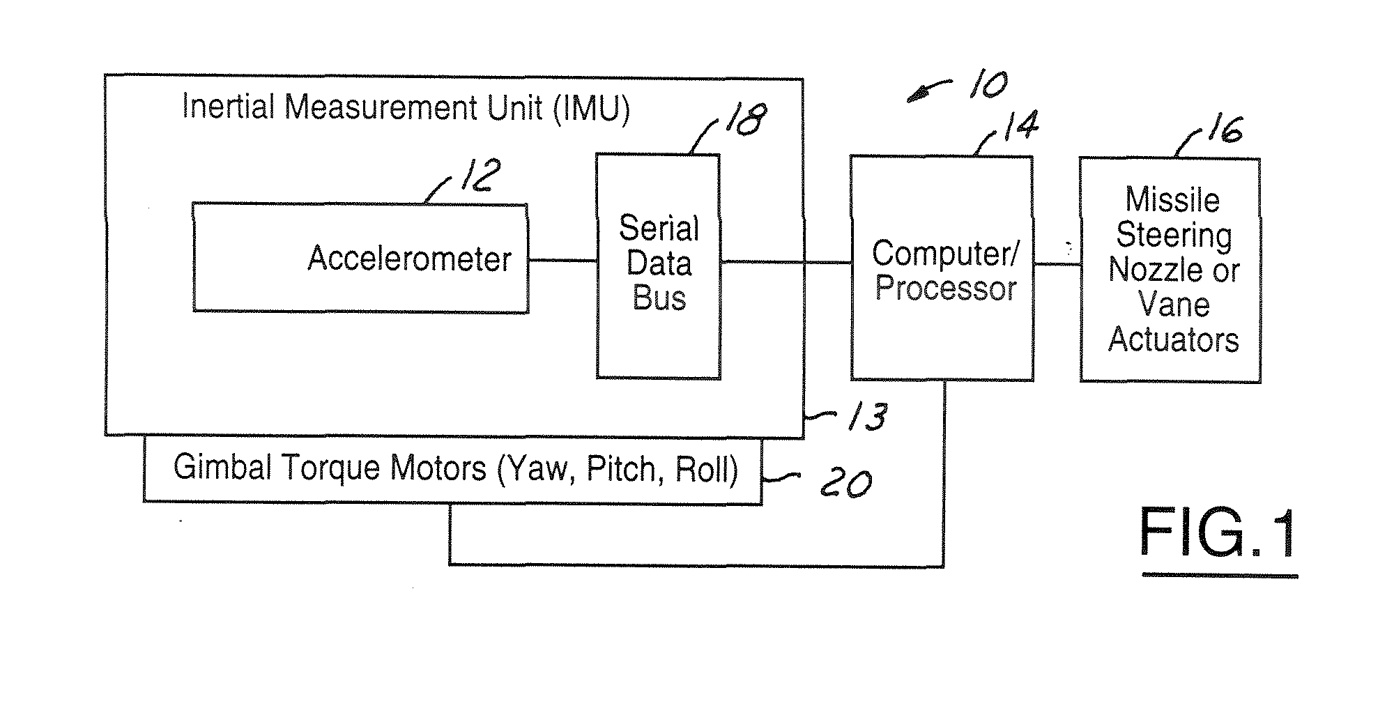
Referring to FIG. 1, the system 10, which is an aerospace, accelerometer system, including an angular and linear accelerometer system 12 within an inertial measurement unit 13, is illustrated. The aerospace system 10 is merely an illustrative example of an accelerating object and not meant to be limiting. For example, the present angular and linear accelerometer 12 could be implemented in any accelerating object to sense acceleration forces, including any type of vehicle or missile system, such as a Minuteman III missile system or a Scud missile system.

The illustrated aerospace system 10 includes an inertial mea...


PUM


Abstract

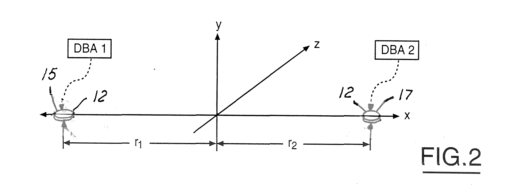
An accelerometer includes an inertial platform maintaining an attitude in response to a platform stabilizing controller signal and defining a spin axis and a reference plane. An accelerometer, coupled to the inertial platform a distance from the spin axis, defines a flex axis. The accelerometer generates an accelerometer signal in response to acceleration of the accelerometer. A second accelerometer defines a second flex axis, and is also coupled to the inertial platform a distance from the spin axis. The second accelerometer generates a second accelerometer signal in response to acceleration of the second accelerometer. A controller receives the first accelerometer signal and the second accelerometer signal and generates a linear acceleration signal in response to a sum of the first accelerometer signal and the second accelerometer signal and generates an angular acceleration signal from the difference. The controller further generates the platform stabilizing controller signal in response to the first acceleration signal and the second acceleration signal.

Description

BACKGROUND OF INVENTION The present invention relates generally to accelerometers, and more particularly, to a variable capacitance accelerometer generating angular and linear signals. It is well known that capacitive accelerometers measure the acceleration, vibration and the inclination of objects to which they are attached. These objects typically include missiles, spacecraft, airplanes and automobiles. In general, capacitive accelerometers change electrical capacitance in response to acceleration forces and vary the output of an energized circuit. Capacitive accelerometer systems generally include sensing elements, including capacitors, oscillators, and detection circuits. The sensing elements include at least two parallel plate capacitors functioning in differential modes. The parallel plate capacitors generally operate in sensing circuits and alter the peak voltage generated by oscillators when the attached object undergoes acceleration. When subject to a fixed or constant...

Claims


Application Information

Patent Timeline
Patent Type & Authority Applications(United States)
IPC IPC(8): G01P15/08G01P15/125G01P15/18
CPCG01P15/0888G01P15/18G01P15/125
Inventor CAMPBELL, RAY F.WADA, JOAN D.
Owner THE BOEING CO
Learn More